BigWorld Technology 2.1. Released 2012.
Copyright © 1999-2012 BigWorld Pty Ltd. All rights reserved.
This document is proprietary commercial in confidence and access is restricted to authorised users. This document is protected by copyright laws of Australia, other countries and international treaties. Unauthorised use, reproduction or distribution of this document, or any portion of this document, may result in the imposition of civil and criminal penalties as provided by law.
Table of Contents
- 1. Introduction
- 2. World Editor
- 2.1. Menu items
- 2.2. Toolbar
- 2.3. Status bar
- 2.4. Gizmos
- 2.5. Keyboard shortcuts
- 2.6. Mouse controls
- 2.7. Dialog boxes
- 2.7.1. Browse For Folder dialog box
- 2.7.2. Changed Files dialog box
- 2.7.3. Convert Space dialog box
- 2.7.4. New Space dialog box
- 2.7.5. New Space Folder dialog box
- 2.7.6. Noise Setup dialog box
- 2.7.7. Placement Controls dialog box
- 2.7.8. RAW Terrain Import dialog box
- 2.7.9. Resize Terrain Blends dialog box
- 2.7.10. Set Slider Limits dialog box
- 2.7.11. WorldEditor Shortcuts dialog box
- 2.8. Chunk visualisation modes
- 2.9. Assets
- 2.10. Panel summary
- 2.10.1. Object panel
- 2.10.2. Terrain Texturing panel
- 2.10.3. Terrain Height panel
- 2.10.4. Terrain Filtering panel
- 2.10.5. Terrain Mesh Cut/Repair panel
- 2.10.6. Terrain Import/Export panel
- 2.10.7. Project panel
- 2.10.8. Asset Browser panel
- 2.10.9. Scene Browser panel
- 2.10.10. Post-Processing panel
- 2.10.11. Properties panel
- 2.10.12. Chunk Textures panel
- 2.10.13. General Options panel
- 2.10.14. Navigation panel
- 2.10.15. Weather Preview panel
- 2.10.16. Environment Options panel
- 2.10.17. Histogram panel
- 2.10.18. BigWorld Messages panel
- 2.11. Useful notes
- 2.11.1. Chunks
- 2.11.2. Portals
- 2.11.3. Directional lights for outdoor use only
- 2.11.4. Potential problems placing models and shells
- 2.11.5. Corrupted space map
- 2.11.6. Creating spaces
- 2.11.7. Lock Server (bwlockd) and new spaces
- 2.11.8. Activity logging
- 2.11.9. Patrol path editing with User Data Objects
- 2.11.10. Some useful Python scripts
- 3. Model Editor
- 4. Particle Editor
- 5. Tools Consoles
- 6. Starting the Tools
- 7. Asset Browser
- 8. Meta Data
- 9. Panel System
- 10. Offline Processor
- 11. NavGen
- 11.1. Configuring the space to use NavGen
- 11.2. NavPoly Generator menu items
- 11.3. NavPoly Generator status bar
- 11.4. NavPoly Generator keyboard shortcuts
- 11.5. NavPoly Renderer keyboard shortcuts
- 11.6. NavPoly Generator mouse controls
- 11.7. NavPoly Renderer mouse controls
- 11.8. Statistics dialog box
- 11.9. Cluster Generate dialog box
- 11.10. Navpoly Info dialog box
- 11.11. Navpolys, vertices and adjacency
- 11.12. Generating the navmesh on multiple machines
- 11.13. Generating the navmesh
- 11.14. Moving entities
- 11.15. Changing settings
- 11.16. Discontinuous navmesh
- 12. 3ds Max and Maya Exporters
- 13. Lock Server (BWLockD)
This document describes the tools available in BigWorld from a technical point of view. For details on how to make the best use of them, alongside suggestions, see the document Content Creation Manual.
Note
For details on BigWorld terminology, see the document Glossary of Terms.
Table of Contents
- 2.1. Menu items
- 2.2. Toolbar
- 2.3. Status bar
- 2.4. Gizmos
- 2.5. Keyboard shortcuts
- 2.6. Mouse controls
- 2.7. Dialog boxes
- 2.7.1. Browse For Folder dialog box
- 2.7.2. Changed Files dialog box
- 2.7.3. Convert Space dialog box
- 2.7.4. New Space dialog box
- 2.7.5. New Space Folder dialog box
- 2.7.6. Noise Setup dialog box
- 2.7.7. Placement Controls dialog box
- 2.7.8. RAW Terrain Import dialog box
- 2.7.9. Resize Terrain Blends dialog box
- 2.7.10. Set Slider Limits dialog box
- 2.7.11. WorldEditor Shortcuts dialog box
- 2.8. Chunk visualisation modes
- 2.9. Assets
- 2.10. Panel summary
- 2.10.1. Object panel
- 2.10.2. Terrain Texturing panel
- 2.10.3. Terrain Height panel
- 2.10.4. Terrain Filtering panel
- 2.10.5. Terrain Mesh Cut/Repair panel
- 2.10.6. Terrain Import/Export panel
- 2.10.7. Project panel
- 2.10.8. Asset Browser panel
- 2.10.9. Scene Browser panel
- 2.10.10. Post-Processing panel
- 2.10.11. Properties panel
- 2.10.12. Chunk Textures panel
- 2.10.13. General Options panel
- 2.10.14. Navigation panel
- 2.10.15. Weather Preview panel
- 2.10.16. Environment Options panel
- 2.10.17. Histogram panel
- 2.10.18. BigWorld Messages panel
- 2.11. Useful notes
- 2.11.1. Chunks
- 2.11.2. Portals
- 2.11.3. Directional lights for outdoor use only
- 2.11.4. Potential problems placing models and shells
- 2.11.5. Corrupted space map
- 2.11.6. Creating spaces
- 2.11.7. Lock Server (bwlockd) and new spaces
- 2.11.8. Activity logging
- 2.11.9. Patrol path editing with User Data Objects
- 2.11.10. Some useful Python scripts
World Editor is BigWorld's tools to quickly create and edit worlds.
This chapter describes the options available in World Editor's environment.
For more details on how to perform common tasks in World Editor, see the document Content Creation Manual which can be accessed from inside the World Editor by pressing F1 or by selecting the Help → Content Creation menu item[1].
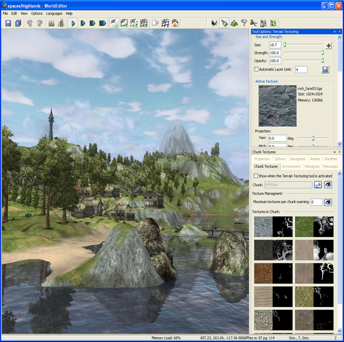
World Editor window
For details on how to start this and other BigWorld tools, see Starting the Tools.
The list below describes the menu items available in World Editor:
File → New spaceB
Opens the New Space dialog box, where the user can create a new space, specifying its name, path, size, and alternatively, advanced terrain features.
After creation, the space will be displayed in the viewport.
For details, see New Space dialog box.
File → Open spaceB
Opens the Browse For Folder dialog box, where the user can specify the space to be loaded.
For details, see Browse For Folder dialog box.
File → Reload all chunksB
Reloads all chunks and associated data of the current space.
File → Reload all textures
Reloads all textures currently used by World Editor, to refresh textures changed by external applications.
File → Regenerate Terrain LODs
Reloads the terrain textures and applies them to all chunks in the space.
File → Regenerate Thumbnails
Regenerates thumbnails (as viewed in the Project View) for all chunks in the space.
File → Invalidate All Chunks
Invalidates all chunks in the space so that their secondary data (e.g. shadow maps or terrain LODs) need to be recalculated.
File → Save
Saves all modified terrain and chunk files, plus the project's space map, if it was changed — this operation can be stopped by pressing EscC.
Secondary data (such as terrain shadow information, static lighting data, and chunk thumbnails) that has already been calculated will also be saved, but no calculation is done. A list of chunks whose secondary data have been calculated will be stored in the space's space.cleanlist file.
The next time the File → Process Data menu item is selected, the necessary calculation will be performed on all chunks that are dirty.
Performs the same function as the Save toolbar buttonA (
 ).
).File → Process data
Calculates derived data and saves all modified data — this operation can be stopped by pressing EscC.
While this process takes longer than a regular save, it makes the space ready with all information required to run the game.
Performs the same function as the Process All Data toolbar buttonA (
 ).
).File → Convert to advanced terrainB
Opens the Convert Space dialog box, where the user can convert a simple terrain space to one with advanced terrain features.
For details, see Convert Space dialog box.
File → Resize terrain texture blendsB
Opens the Resize Terrain Blends dialog box, where the user change the resolution of the texture layers blend map.
For details, see Resize Terrain Blends dialog box.
File → Recent spaces
Opens a sub-menu with a list of recent spaces.
For details, see Resize Terrain Blends dialog box.
File → ExitB
Closes the application.
Edit → Undo
Undoes the most recent world-changing action.
Multiple actions can be undone. The undo list extends to the state of the world when World Editor was last started.
Each world-changing action that is undone is added to the redo list.
Performs the same function as the Undo toolbar buttonA (
 ).
).Note
Only actions that effectively change the world are added to the undo list.
Actions added to the undo list:
Applying texture to terrain.
Placing/deleting/moving/ rotating/scaling an object.
Cutting a hole in terrain.
Actions not added to the undo list:
Changing the brush size and/or strength.
Changing Object panel's Selection Filter.
Changing camera height and/or angle.
Edit → Redo
Redoes the most recently undone world-changing action.
Multiple actions can be redone.
The redo list contains one entry for each undone world-changing action.
Performs the same function as the Redo toolbar buttonA (
 ).
).Edit → Clear undo/redo history
Clears the undo list and the redo list.
Edit → Select all
Selects all objects in the space that match the current selection in Object panel's Selection Filter drop-down list box (for details on this drop-down list box, see Object panel).
Edit → Deselect all
Deselects all selected objects.
Edit → Save shell as template
Saves the selected shells as a template, adding the extension .template to the file name.
The template file will contain both chunk and lighting information.
If the user wants to also save models and/or shells, then save the selection as a prefab (via the Edit → Save Selection As Prefab menu item).
Edit → Save selection as prefab
Saves the current selection as a .prefab file, which can then later be used to place a copy of the items in the terrain.
Prefabs are elements such as objects, models, lights, shells, and items that can be saved in World Editor. They allow the artist to save a carefully arranged group of items to a single file, so that it can be used elsewhere within the world without having to arrange the objects a second time.
While a template can only contain lighting information, a prefab can contain also models and other objects.
The user may place existing prefabs by selecting the Asset Browser panel's Prefabs virtual folder. For details, see Asset Browser panel.
Edit → Hide Selection
Hide the selected items. The hidden state affects items in the editor only, it has no effect on the client or the server.
Edit → Unhide Selection
Unhide the selected items. To select hidden items, select them in the Scene Browser panel (see Scene Browser panel), or use the Hidden Objects selection filter in the Object panel (see Object panel).
Edit → Unhide All Selectable
Unhide all the hidden items in the space that are selectable according to the Selection Filter of the Object panel (see Object panel).
Edit → Unhide All
Unhide all the hidden items in the space.
Edit → Freeze Selection
Freeze the selected items. The frozen state affects items in the editor only, it has no effect on the client or the server.
Edit → Unfreeze Selection
Unfreeze the selected items. To select frozen items, select them in the Scene Browser panel (see Scene Browser panel), or use the Frozen Objects selection filter in the Object panel (see Object panel).
Edit → Unfreeze All Selectable
Unfreeze all the frozen items in the space that are selectable according to the Selection Filter of the Object panel (see Object panel).
Edit → Unfreeze All
Unfreeze all the frozen items in the space.
View → Toolbars → Main toolbar, View → Toolbars → Tools
Toggles the toolbar visibility.
For details on toolbars, see Toolbar.
View → Status bar
Toggles the status bar visibility.
For details on the status bar, seeStatus bar.
View → Show tool options panelA
Toggles the visibility of the Tool Options panel, which displays the settings for the tool selected in the toolbar.
For details on each tool panel see:
Object panel — See Object panel.
Terrain Texturing panel — See Terrain Texturing panel.
Terrain Height panel — See Terrain Height panel.
Terrain Filtering panel — See Terrain Filtering panel.
Terrain Mesh Cut/Repair panel — See Terrain Mesh Cut/Repair panel.
Terrain Import/Export panel — See Terrain Import/Export panel.
Project panel — See Project panel.
View → Show asset browser A
Displays/activates the panel (for details, see Asset Browser panel).
View → Show scene browserA
Displays/activates the panel (for details, see Scene Browser panel).
View → Show post processing panel A
Displays/activates the panel (for details, see Post-Processing panel).
View → Show properties panel A
Displays/activates the panel (for details, see Properties panel).
View → Show general options panel A
Displays/activates the panel (for details, see General Options panel).
View → Show navigation panel A
Displays/activates the panel (for details, see Navigation panel).
View → Show weather options panel A
Displays/activates the panel (for details, see Weather Preview panel).
View → Show environment options panel A
Displays/activates the panel (for details, see Environment Options panel).
View → Show histogram panel A
Displays/activates the panel (for details, see Histogram panel).
View → Show messages panel A
Displays/activates the panel (for details, see BigWorld Messages panel).
View → Show chunk textures panel A
Displays/activates the panel (for details, see Chunk Textures panel).
View → Show panelsA
Toggles the visibility of all panels.
View → Load default panel layoutA
Closes all customised panels, and displays World Editor's default panel.
View → Load most recent panel layoutA
Closes all current panels, and displays the customised panel layout previously used.
Options → Save camera position
Saves the current camera position to space.localsettings file.
The camera will be initialised with this position on the next session of World Editor.
Options → Save start position
Saves the current camera position to space.settings configuration file.
Your game can read this information as the starting point for the game character. Useful possibly only during development.
Options → Enable Umbra
Toggles Umbra occlusion culling
Options → Preview Default Weather When Opening a Space
If this option is enabled, then when you open a space in World Editor, the default weather selected for that space will automatically play. This is to enhance the WYSIWYG experience. If you find instead that this gets in your way while editing, you can turn this off. You can still select weather to preview in the Weather panel.
Languages → List of available languages
Selects the language to use in the tool.
This list is compiled based on the LanguageName tags present in the XML files in the
<res>/helpers/languages folder and in the file pointed by the language tag in bigworld/tools/worldeditor/options.xml.Help → About World Editor
Opens the World Editor About dialog box.
Help → Tools Reference Guide
Opens this document.
Help → Content creation
Opens the document Content Creation Manual.
Help → Shortcuts
Opens the Keyboard Shortcuts dialog box.
For details on this dialog box, see WorldEditor Shortcuts dialog box.
Help → Request feature/report bug
Opens your e-mail program, with To: field automatically set to BigWorld's support e-mail address, and Subject: set to World Editor - Feature Request / Bug Report.
A — For details on the panel system and its terminology, see Panel System.
B — If there were changes to the world, user will be prompted to choose between saving the changes before proceeding, processing changes then saving before proceeding, proceeding without saving changes, or cancelling the operation. For details, see Changed Files dialog box.
C — For details, see Keyboard shortcuts.
The list below describes the toolbar buttons available in World Editor:
- — Save
Saves the data, without recalculating shadow/lighting/thumbnail information.
Performs the same function as the File → Save menu item.A
- — Process all
data
Recalculates shadow/lighting/thumbnail information, then saves them.
Performs the same function as the File → Process Data menu item.A
- — Undo
Undoes the most recent action.
Performs the same function as Edit → Undo menu item.A
- — Redo
Redoes the most recent undone action.
Performs the same function as Edit → Redo menu item.A
 — Orthographic
view
— Orthographic
viewSets the camera to top-down view.
In this mode, the mouse and keys will move along the x- and z- axes (where the y-axis is considered up when standing on the terrain).
For details on camera movement while in this mode, see Mouse controls.
 — Player preview
mode
— Player preview
modeToggles the player walkthrough mode, in which the camera moves in the world as if attached to the player.
The height of the camera on this mode is specified by the Navigation panel's Camera Height field (for details, see Navigation panel).
This button performs the same function as the Navigation panel's Player Preview Mode check box.
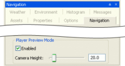
Navigation panel
 — Slow,
 — Medium speed,
 — Fast,
 — Super
Specifies how fast the camera travels in response to appropriate key events (keys Q, W, E, A, S, and D).C
If Caps Lock is on, then the camera speed will be boosted.
Camera speed can also be set to Slow, Medium, Fast and Super Fast by the keyboard shortcuts Ctrl+1, Ctrl+2, Ctrl+3, and Ctrl+4, respectively.
 — Normal,
 — Chunk borders,
 — Pole markers,
 —
Wireframe
—
WireframeToggles between the various chunk visualisation modes.
For details, see Chunk visualisation modes.
 — Edit in external
editor
— Edit in external
editorOpens the current selected item in an external editor.
After saving the item in the editor, World Editor will automatically reload it to reveal the changes.
Currently, we only support particle systems (edited in Particle Editor) and models (edited in Model Editor).
 — Draw terrain as
wireframe
— Draw terrain as
wireframeDraws the terrain mesh as wireframe.
Performs the same function as the General Options panel's, Show list box's, Terrain → Wireframe item (for details on this panel, see General Options panel).
 — Hide/show outside
objects
— Hide/show outside
objectsToggles the visibility of all outside objects.
 — Hide/show navigation
mesh
— Hide/show navigation
meshToggles the visibility of the navigation mesh.
 — Object
toolB
— Object
toolBActivates the Object mode — for details, see Object panel. This mode is also activated by pressing 1C.
 — Terrain texture
toolB
— Terrain texture
toolBActivates the Terrain texture mode — for details, see Terrain Texturing panel. This mode is also activated by pressing 2C.
 — Terrain height
toolB
— Terrain height
toolBActivates the Terrain height mode — for details, see Terrain Height panel. This mode is also activated by pressing 3C.
 — Terrain filter
toolB
— Terrain filter
toolBActivates the Terrain filter mode — for details, see Terrain Filtering panel. This mode is also activated by pressing 4C.
 — Terrain mesh cut/repair
toolB
— Terrain mesh cut/repair
toolBActivates the Terrain mesh cut/repair mode — for details, see Terrain Mesh Cut/Repair panel. This mode is also activated by pressing 5C.
 — Terrain import/ export
toolB
— Terrain import/ export
toolBActivates the Terrain import/export mode — for details, see Terrain Import/Export panel. This mode is also activated by pressing 6C.
 — Project
toolB
— Project
toolBActivates the Project mode — for details, see Project panel. This mode is also activated by pressing 7C.
A — For details, see Menu items.
B — It also displays/activates the tool's panel. For details on panels, see Panel System.
C — For details, see Keyboard shortcuts.
The status bar displays information about the current world, display settings, and mouse positioning.
A typical status bar is illustrated below:

World Editor status bar
The list below describes the pieces of information displayed in the status bar, as they appear:
Memory Load (in the example, 25%)
System memory load.
Mouse pointer position (in the example, -227.00, 179.70, -15.30)
Position of the mouse pointer, in world coordinates.
Chunk identification (in the example, fffdffffo)
ID of the chunk over which the mouse is located.
Models in chunk (in the example, m:14)
Number of models in the chunk over which the mouse is located.
Primitive groups in chunk (in the example, pg: 20)
Number of primitive groups in chunk over which the mouse is located.
Current snap mode (in the example, free)
Displays the current method for snapping objects in the world. This is specified in the Object panel's Object Grid Snaps group box (for details, see Object panel.).
Triangles rendered (in the example, 1016587 tris.)
Number of triangles currently being rendered in the scene.
Frame rate (in the example, 13.3 fps.)
Frame rate used to display the scene.
Loaded chunks (in the example, 684 chunks loaded)
Number of loaded chunks.
By default, the Chunk Manager only loads the chunks in the area around the camera, up to the far plane (configured in the General Options panel's Far Plane field — for details, see General Options panel).
Dirty chunk information (in the example, (Navmesh: 682 Shadow:474 Thumbnail: 476))
Information about number and type of dirty chunks.
This lists the number of chunks which have dirty generated data of various types. Currently these types are:
Lighting: Pre-generated vertex lighting data for fixed objects, indoors and optionally outdoors.
NavMesh: Navigation mesh data generated by Offline Processor or NavGen.
Shadow: Terrain horizon shadow maps.
TerrainLod: Terrain LOD texture used for geo-mipmapping.
Thumbnail: Overhead snapshot thumbnail of the chunk, generated and used in the Project View of World Editor.
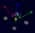
World Editor provides both context-sensitive gizmos and keyboard-activated gizmos that allow the configuration of world items. They are described in the sections below.
Displayed by default on all world items and represented by red-green-blue axes (or red-green axis if the Object panel's Locking Mode groups box's Terrain option button is selected) ending in a arrow, this gizmo allows the item to be repositioned in the world.
Please note that if the Objects panel's Drag On Select check box is selected, then items can be moved by simply dragging them.
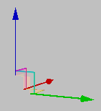
Movement gizmo (Free and Obstacle modes)
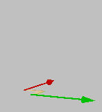
Movement gizmo (Terrain mode)
Displayed automatically when a user data object with one or more UDO_REF properties is selected. This gizmo contains two circles, which when dragged and dropped on top of another user data object creates a link between the two, and, if the user data object editor script implements it, two crosses that when dragged allow cloning the user data object.
For details on using this gizmo, see Patrol path editing with User Data Objects.
User data object linking gizmo
Displays automatically when an entity that contains one or more UDO_REF properties is selected. This gizmo is composed of two circles that can be dragged to a user data object to establish link to it, from the entity.
For details on how to configure an entity to support linking to user data objects and how to use this gizmo, see Patrol path editing with User Data Objects.
Entity linking gizmo
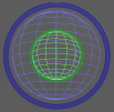
Activated by the Shift keyboard shortcut and represented by red-green-blue circles, this gizmo allows the item to be rotated in all directions.
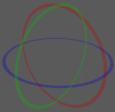
Rotation gizmo
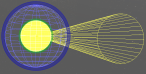
Note
Spot lights have an additional yellow circle that allows the user to change the cone angle property.
Rotation gizmo for spot lights
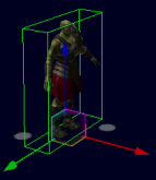
Activated by the Alt keyboard shortcut and represented by red-green-blue axes ending in a square (for regular scale gizmo) and a white circle (for uniform scale gizmo), this gizmo allows the item to be scaled.
Dragging one of the squares at the end of an axis rescales the item only in that dimension. Dragging the white circle inwards or outwards uniformly shrinks or enlarges the item, respectively.
Scale gizmo
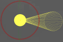
Note
Lights have a different scale gizmo, with a green circle representing the inner radius and a blue circle representing the outer radius.
Spot lights have an additional yellow circle that allows the user to change the cone angle property.
Scale gizmo for lights
Scale gizmo for spot lights
Activated by pressing Shift while the Terrain Texture toolbar buttonA —— is selected or by clicking the Terrain Texturing panel's  buttonB, this gizmo
contains the following elements (each updating a different field in the
panel):
buttonB, this gizmo
contains the following elements (each updating a different field in the
panel):
Projection gizmo (composed of red, green, and blue circles).
Red circle — updates the Roll field.
Green circle — updates the Pitch field.
Blue circle — updates the Yaw field.
Scale gizmo (composed of red and green cubes and a red- and green-sided rectangle or grid).
Red cube — updates the V field.
Green cube — updates the U field.
A — For details, see Toolbar.
B — For details, see Terrain Texturing panel.

Texture projection/scale gizmo
The list of World Editor's keyboard shortcuts can be displayed via the Help → Shortcuts menu item (for details, see Menu items).
The sections below list the World Editor's keyboard shortcuts.
F1
Displays the World Editor Shortcuts page, which can be left by pressing Esc.
F4
Cycles through object locking modes:
Free
Terrain
Obstacle
Performs the same function as the Object panel's Locking Mode group boxA.

Object panel's Locking Mode group box
Ctrl+F5
Activates the Realtime Profiling console, which can be left by pressing Esc (for details, see Realtime Profiling console).
F6
Cycles through the chunk visualisation modes:
Normal — same as the
 toolbar button.
Chunk borders — same as the
 toolbar button.
Pole markers — same as the
 toolbar button.
Wireframe — same as the
 toolbar button.
Performs the same function as the Chunk Visualisation toolbar buttons (for details, see Toolbar).
For details, see Chunk visualisation modes.
Ctrl+F7
Activates the Debug (Watcher) console, which can be left by pressing Esc (for details, see Debug (Watcher) console).
F8
Cycles through coordinate systems:
World
Local
View
Performs the same function as the Object panel's Coordinate System group boxA.
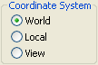
Object panel's Coordinate System group box
F9
If Terrain Texture ToolB —
 — is
selected
— is
selectedRecalculates detail objects, such as flora, based on the texture predominant in the terrain.
For more details on flora calculation, see the document Content Creation Manual's lesson Create and Use Flora (the document is accessed by pressing F1 or by selecting the Help → Content Creation menu item — for details, see Menu items).
F11
Activates the Histogram console, which can be left by pressing Esc (for details on this console, see Histogram console).
A — For details, see Object panel.
B — For details, see Terrain Texturing panel, and Toolbar.
Alt
If at least one object is selected
If the mouse is being dragged (using the left button)
Deselects the items delimited by the area over which the mouse is dragged.
Otherwise
While pressed, the key activates the scale gizmos (NOTE: the key does not toggle a scale mode).
The uniform scale gizmo is represented by a circle, and causes the object to have all its dimensions uniformly resized. The regular scale gizmo is represented by the usual red-green-blue axis gizmo, and causes the object to be rescaled only on the selected dimension.
For lights, the scale gizmo for inner radius (represented by a green circle) and outer radius (represented by a blue circle) are activated. For spot lights, the gizmo for the property cone angle (represented by a yellow area inside the gizmo for inner radius) is also activated.
The selected object can then be shrunk or enlarged, up to a maximum size of 100 metres.
The scale gizmos use the Object panel's Coordinate system and Locking Mode group boxes to determine which axis to scale on and whether to snap the objects while scaling (for details, see Object panel).
If Terrain Texture Tool toolbar buttonC —
— is
selectedActivates the texture sampler tool (indicated by the
 cursor icon), which samples the dominant
texture of the chunk under the cursor — the Terrain Texturing panel's Active Texture fieldC will be
updated accordingly.
cursor icon), which samples the dominant
texture of the chunk under the cursor — the Terrain Texturing panel's Active Texture fieldC will be
updated accordingly.If Terrain Texture Height toolbar buttonE —
 — is
selected
— is
selectedActivates the height picker tool (indicated by the
 cursor icon), which samples the height
underneath the cursor and assigns it to the Terrain Height panel's Explicit Height field (for details, see
Terrain Height panel).
cursor icon), which samples the height
underneath the cursor and assigns it to the Terrain Height panel's Explicit Height field (for details, see
Terrain Height panel).If Terrain Import/Export toolbar buttonD —
 — is
selected
— is
selectedActivates the height picker tool (indicated by the
cursor icon), which samples the maximum
height of the region selected by dragging the mouse and assigns
it to the Terrain Import/Export
panel's Maximum Height field
(for details, see Terrain Import/Export panel).If Debug (Watcher) consoleB is active
If [0-9] key in the alphanumeric keypad is pressed:
Selects item 40+[0-9], or 50+[0-9] (if Shift is pressed).
Alt+Ctrl
If Terrain Texture Tool toolbar buttonC —
— is
selectedActivates the texture/opacity sampler tool (indicated by the
 cursor icon), which samples the dominant
texture of the chunk under the cursor and its opacity — the
Terrain Texturing panel's
Active Texture and Opacity fieldsC will be
updated accordingly.
cursor icon), which samples the dominant
texture of the chunk under the cursor and its opacity — the
Terrain Texturing panel's
Active Texture and Opacity fieldsC will be
updated accordingly.
Alt+Shift
If Terrain Texture Tool toolbar buttonC —
— is
selectedActivates the texture projection tool (indicated by the
 cursor icon — a red- and green-sided
square indicates the clicked area), which adjusts the Terrain Texturing panel's Projection fieldsC to the
values of that of the terrain under the cursor.
cursor icon — a red- and green-sided
square indicates the clicked area), which adjusts the Terrain Texturing panel's Projection fieldsC to the
values of that of the terrain under the cursor.If Debug (Watcher) consoleB is active
If [0-9] key in the alphanumeric keypad is pressed:
Selects item 50+[0-9].
Alt+Page Down
If Debug (Watcher) consoleB is active
If the watcher is in Edit mode, then decreases the watcher's value by 1,000.
Alt+Page Up
If Debug (Watcher) consoleB is active
If the watcher is in Edit mode, then increases the watcher's value by 1,000.
Ctrl
If at least one object is selected
While pressed, the key enables the selection of multiple objects (NOTE: the key does not toggle an additive selection mode).
If used in conjunction with the mouse scroll wheel
Rotates the selected shells according to the snapped portals.
If Debug (Watcher) consoleB is active
If [0-9] key in the alphanumeric keypad is pressed:
Selects item 20+[0-9], or 30+[0-9] (if Shift is pressed).
If Terrain Height Tool toolbar buttonE —
— is
selectedNote: This is only valid if the left Ctrl key is pressed.
Activates the explicit height brush (indicated by a green square), which immediately sets the terrain height to the value specified in the Explicit Height field (if the Absolute option button is selected), or immediately increases the terrain height by the value specified in the Explicit Height field (if the Relative option button is selected).
For details on absolute and relative explicit height modes, see Terrain Height panel.
If Terrain Import/Export toolbar buttonD —
— is
selectedActivates the height picker tool (indicated by the
cursor icon), which samples the minimum
height of the region selected by dragging the mouse and assigns
it to the Terrain Import/Export
panel's Minimum Height
field.
Ctrl+Alt
See the entry Alt+Ctrl in this list.
Ctrl+Shift
If Debug (Watcher) consoleB is active
If [0-9] key in the alphanumeric keypad is pressed:
Selects item 30+[0-9].
Ctrl+Page Down
If Debug (Watcher) consoleB is active
If the watcher is in Edit mode, then decreases the watcher's value by 100.
Ctrl+Page Up
If Debug (Watcher) consoleB is active
If the watcher is in Edit mode, then increases the watcher's value by 100.
Shift
If at least one object is selected
While pressed, the key activates the rotation gizmo (NOTE: the key does not toggle a rotation mode).
The rotation gizmo uses the Object panel's Coordinate system and Locking Mode group boxes to determine which axis to rotate around and whether to snap the objects while rotating (for details, see Object panel).
If Terrain Texture Tool toolbar buttonC —
— is
selectedActivates the texture projection/scale gizmo (for details, see Terrain Texturing gizmos). The gizmo can also be activated by clicking the
button on top of the Terrain Texturing panelC.If Terrain Import/Export toolbar buttonD —
— is
selectedLocks the selected region being dragged to chunk boundaries.
If Debug (Watcher) consoleB is active
If [0-9] key in the alphanumeric keypad is pressed:
Selects item 10+[0-9], 30+[0-9] (if Ctrl is pressed), or 50+[0-9] (if Alt is pressed).
Shift+Enter
If Debug (Watcher) consoleB is active and watcher is in edit mode
Displays the watcher modification history.
Shift+Alt
See the entry Alt+Shift in this list.
Shift+Page Down
If Debug (Watcher) consoleB is active
If the watcher is in Edit mode, then decreases the watcher's value by 100.
Shift+Page Up
If Debug (Watcher) consoleB is active
If the watcher is in Edit mode, then increases the watcher's value by 100.
A — For details, see Toolbar.
B — Activated by F7 (for details on the Python console, see Python console).
C — For details, see Terrain Texturing panel.
D — For details, see Terrain Import/Export panel.
E — For details, see Terrain Height panel.
Backspace
If Debug (Watcher) consoleC is active
Returns the list to the previous branch of the watcher tree.
Caps Lock
ON
Increases the current camera speed. It accelerates the camera movement, which speed is set by keyboard shortcuts (Ctrl+1, Ctrl+2, Ctrl+3, and Ctrl+4), or by the Camera Speed toolbar buttons (
 ,
, ,
, , and
, and  ).
).OFF
Restores camera to the speed set by keyboard shortcuts or by the Camera Speed toolbar buttonsA.
Delete
Deletes the selected objects.
Enter
If Object Tool toolbar buttonB —
 — is
selected
— is
selectedPlaces the selected object under the mouse cursor.
If Python consoleE
Executes the Python command, or exits the console if no command was specified.
If Realtime Profiling consoleD is active
Expands or collapses the profiling element currently selected — elements with children are indicated by an ellipsis (…) next to it.
If Debug (Watcher) consoleC is active
If the selected node is not a leaf
Navigates one level down in the watcher tree.
If the selected node is a leaf
Opens the selected watcher for editing, or accepts the typed value if it is already in Edit mode.
If watcher is in Editor mode and Shift is pressed
Displays the watcher modification history.
Esc
Deselects the selected objects.
If the File → Save or File → Process Data menu item has been selected, and is still saving/processing
Cancels the operation (for details, see Menu items).
If any console is active
Exits the console.
NOTE: The different modes and consoles are activated in the following way:
Help mode — F1
Realtime profiling console — F5 (for details, see Realtime Profiling console)
Debug (Watchers) console — F7 (for details, see Debug (Watcher) console)
Histogram console — F11 (for details, see Histogram console)
Python console — Ctrl+P (for details, see Python console)
If Debug (Watcher) consoleC is active
If the watcher is in Edit mode
Leaves Edit mode.
If the watcher is not in Edit mode
Exits the console.
Home
If Realtime Profiling consoleD is active
Scrolls the list to display the first page.
If Debug (Watcher) consoleC is active
Returns the list to the root of the watcher tree.
Page Down
If Realtime Profiling consoleD is active
Moves the selection to the next element in the list.
Performs the same function as the ] (square right bracket) keyboard shortcut.
If Debug (Watcher) consoleC is active
If the watcher is not in Edit mode
Moves the selection to the next item in the list.
If the watcher is in Edit mode
Decreases the watcher's value by 1, 10 (if Shift is pressed), 100 (if Ctrl is pressed), or 1,000 (if Alt is pressed).
Page Up
If Realtime Profiling consoleD is active
Moves the selection to the previous element in the list.
Performs the same function as the [ (square left bracket) keyboard shortcut.
If Debug (Watcher) consoleC is active
If the watcher is not in Edit mode
Moves the selection to the previous item in the list.
If the watcher is in Edit mode
Increases the watcher's value by 1, 10 (if Shift is pressed), 100 (if Ctrl is pressed), or 1,000 (if Alt is pressed).
A — For details, see Toolbar.
B — For details, see Object panel, and Toolbar.
C — Activated by F7 (for details, see Debug (Watcher) console).
D — Activated by F5 (for details, see Realtime Profiling console).
E — Activated by Ctrl+P (for details, see Python console).
Numpad + (Plus sign)
If Realtime Profiling consoleA is active
Scrolls the screen one line down.
If Debug (Watcher) consoleB is active
Scrolls the watcher list down.
, (Comma)
If Terrain Filter Tool toolbar buttonC —
 — is
selected
— is
selectedSelects the previous item in the Filters list box.
Numpad - (Minus sign)
If Realtime Profiling consoleA is active
Scrolls the screen one line up.
If Debug (Watcher) consoleB is active
Scrolls the watcher list up.
. (Period)
If Terrain Filter Tool toolbar buttonC —
— is
selectedSelects the next item in the Filters list box.
[ (Left square bracket)
If Terrain Texture ToolD —
—, Terrain Height
ToolE ——, Terrain Filter
ToolC ——, or Terrain Mesh
ToolF — — toolbar button is
selected
— toolbar button is
selectedDecreases the brush size.G
If Realtime Profiling consoleA is active
Moves the selection to the profiling element in the list.
Performs the same function as the Page Up keyboard shortcut.I
] (Right square bracket)
If Terrain Texture ToolD —
—, Terrain Height
ToolE ——, Terrain Filter
ToolC ——, or Terrain Mesh
ToolF —— toolbar button is
selectedIncreases the brush size.G
If Realtime Profiling consoleA is active
Moves the selection to the next element in the list.
Performs the same function as the Page Down keyboard shortcutI.
{ (Left curly bracket)
If Terrain Texture ToolD —
—, Terrain Height
ToolE ——, Terrain Filter
ToolC ——, or Terrain Mesh
ToolF —— toolbar button is
selectedDecreases the brush strength.G
} (Right curly bracket)
If Terrain Texture ToolD —
—, Terrain Height
ToolE ——, Terrain Filter
ToolC ——, or Terrain Mesh
ToolF —— toolbar button is
selectedIncreases the brush strength.G
~ (Tilde)
Toggles the player walkthrough mode.
This mode can also be toggled by the Player Preview Mode toolbar buttonH —
 —, or by the Navigation panel's Player Preview Mode group box's Enabled check
box.I
—, or by the Navigation panel's Player Preview Mode group box's Enabled check
box.I
A — Activated by F5 (for details, see Realtime Profiling console).
B — Activated by F7 (for details, see Debug (Watcher) console).
C — For details, see Terrain Filtering panel, and Toolbar.
D — For details, see Terrain Texturing panel, and Toolbar.
E — For details, see Terrain Height panel, and Toolbar.
F — For details, see Terrain Mesh Cut/Repair panel, and Toolbar.
G — The mouse pointer must be located somewhere in the viewport for the shortcut to have effect.
H — For details, see Toolbar.
I — For details, see Navigation panel.
Alphanumeric keypad
1
Activates the Object mode — for details, see Object panel. This mode is also activated by the
toolbar
buttonD.2
Activates the Terrain texture mode — for details, see Terrain Texturing panel. This mode is also activated by the
toolbar
buttonD.3
Activates the Terrain height mode — for details, see Terrain Height panel. This mode is also activated by the
toolbar
buttonD.4
Activates the Terrain filter mode — for details, see Terrain Filtering panel. This mode is also activated by the
toolbar
buttonD.5
Activates the Terrain mesh cut/repair mode — for details, see Terrain Mesh Cut/Repair panel. This mode is also activated by the
toolbar
buttonD.6
Activates the Terrain import/export mode — for details, see Terrain Import/Export panel. This mode is also activated by the
toolbar
buttonD.7
Activates the Project mode — for details, see Project panel. This mode is also activated by the
toolbar
buttonD.If Debug (Watcher) consoleB is active
Depending on the key modifier pressed (if any), selects the following item (n is the pressed key):
n10+
n(if Shift is pressed)20+
n(if Ctrl is pressed)30+
n(if Ctrl+Shift is pressed)40+
n(if Alt is pressed)50+
n(if Alt+Shift is pressed)
Numeric keypad
0
If Histogram consoleA is active
Toggles the graphing of luminance.
1
If Histogram consoleA is active
Toggles the graphing of the red component in the RGB histogram.
2
If Histogram consoleA is active
Toggles the graphing of the green component in the RGB histogram.
3
If Histogram consoleA is active
Toggles the graphing of the blue component in the RGB histogram.
4
If Histogram consoleA is active
Toggles the rendering of the scene background on the histograms.
5
If Histogram consoleA is active
Decreases the vertical range ratio of the Luminance and RGB histograms.
6
If Histogram consoleA is active
Increases the vertical range ratio of the Luminance and RGB histograms.
A — Activated by F11 (for details, see Histogram console).
B — Activated by F7 (for details, see Debug (Watcher) console).
C — For details, see Terrain Texturing panel, and Toolbar.
D — For details, see Toolbar.
A
Moves the camera to the left.
B
Toggles the drawing of object's BSPs.
This value can also be set by the General Options panel's, Show list box's, Scenery → BSP itemA.
C
Clones selected objects.
D
Moves the camera to the right.
E
Moves the camera upwards.
If Navigation panel is active
If the Player Preview Mode group box's Enabled check box is selected
Increases the value of the Player Preview Mode group box's Camera Height field.
G
If Object panelC is active
Toggles the snapping of objects to the grid specified in the Object panel.
This value is also set by the Object panel's Object Grid Snaps group box's Enabled check box.
If Realtime Profiling consoleB is active
Draws a graph for the profiling element currently selected.
More than one element can be graphed at any one time. Each one will be assigned a different colour, which will be used to display the element's name, and draw the graph itself.
J
Grants control to the joystick
K
Grants control to the keyboard.
M
Toggles the drag-on-select mode.
This value is also set by the Object panel's Drag On Select check boxC.
Q
Moves the camera downwards.
If the Navigation panelD is active
If the Player Preview Mode group box's Enabled check box is selected
Decreases the value of the Player Preview Mode group box's Camera Height field.
S
Moves the camera backwards.
V
If a shell is selected
While pressed, causes the mouse middle button click to copy selected shell, and links both by a matching portal.
Note: V must be pressed before and during the middle mouse button click.
W
Moves the camera forward.
A — For details, see General Options panel.
B — Activated by F5 (for details, see Realtime Profiling console).
C — For details, see Object panel.
D — For details, see Navigation panel.
Alt+F4
Accesses the File → Exit menu item.C
Alt+Page Down
If Debug (Watcher) consoleB is active and watcher is in edit mode
Decreases the watcher's value by 1,000.
Alt+Page Up
If Debug (Watcher) consoleB is active and watcher is in edit mode
Increases the watcher's value by 1,000.
Alt+[0-9]
If Debug (Watcher) consoleB is active and used alphanumeric keypad
Selects list item 4[0-9].
Alt+Ctrl
If Terrain Texture Tool toolbar buttonA —
— is
selectedActivates the texture/opacity sampler tool (indicated by the
cursor icon), which samples the dominant
texture of the chunk under the cursor and its opacity — the
Terrain Texturing panel's
Active Texture and Opacity fieldsC will be
updated accordingly.
Alt+Ctrl+S
Accesses the File → Process Data menu item.C
Alt+Shift
If Terrain Texture Tool toolbar buttonA —
— is
selectedActivates the texture projection tool (indicated by the
cursor icon — a red- and green-sided
square indicates the clicked area), which adjusts the Terrain Texturing panel's Projection fieldsC to that of
the terrain under the cursor.
Alt+Shift+[0-9]
If Debug (Watcher) consoleB is active and used alphanumeric keypad
Selects list item 5[0-9].
Ctrl+Alt
See the entry Alt+Ctrl in this list.
Ctrl+Alt+S
See the entry Alt+Ctrl+S in this list.
Ctrl+Page Down
If Debug (Watcher) consoleB is active and watcher is in edit mode
Decreases the watcher's value by 100.
Ctrl+Page Up
If Debug (Watcher) consoleB is active and watcher is in edit mode
Increases the watcher's value by 100.
Ctrl+[0-9]
Ctrl+1 turns the Slow Camera toolbar buttonA —
— on.Ctrl+2 turns the Medium Speed Camera toolbar buttonA —
— on.Ctrl+3 turns the Fast Camera toolbar buttonA —
— on.Ctrl+4 turn the Super Fast Camera toolbar buttonA —
— on.If Debug (Watcher) consoleB is active and used alphanumeric keypad
Selects item 2[0-9].
Ctrl+Shift+[0-9]
If Debug (Watcher) consoleB is active and used alphanumeric keypad
Selects item 3[0-9].
Ctrl+A
Accesses the Edit → Select All menu item.C
Ctrl+B
Accesses the Edit → Save Selection As Prefab menu item.C
Ctrl+D
Accesses the Edit → Deselect All menu item.C
Ctrl+H
Accesses the View → Show Panels menu item.C
Ctrl+I
Cycles through the available camera speeds.
This value can also be set by the Camera Speed group of toolbar buttons —
,,,.Ctrl+K
Accesses the File → Reload All Chunks menu item.C
Ctrl+P
Activates the Python console, which can be left by pressing Esc. For details, see Python console.
Ctrl+R
Accesses the File → Reload All Textures menu item.C
Ctrl+S
Accesses the File → Save menu item.C
Ctrl+T
Accesses the Edit → Save Shell As Template menu item.C
Ctrl+Y
Accesses the Edit → Redo menu item.C
Ctrl+Z
Accesses the Edit → Undo menu item.C
Note: The mouse cursor must be over the viewport for shortcut to be enabled.
Shift+Alt
See the entry Alt+Shift in this list.
Shift+Alt+[0-9]
See the entry Alt+Shift+[0-9] in this list.
Shift+Ctrl+[0-9]
See the entry Ctrl+Shift+[0-9] in this list.
Shift+Enter
If Debug (Watcher) consoleB is active and watcher is in edit mode
Displays the watcher modification history.
Shift+Page Down
If Debug (Watcher) consoleB is active and watcher is in edit mode
Decreases the watcher's value by 1.
Shift+Page Up
If Debug (Watcher) consoleB is active and watcher is in edit mode
Increases the watcher's value by 1.
Shift+[
If Terrain Texture Tool toolbar buttonD —
— is
selectedDecreases the brush strength.
Shift+]
If Terrain Texture Tool toolbar buttonD —
— is
selectedIncreases the brush strength.
Shift+F4
Captures a copy of the current scene to bigworld/tools/worldeditor/shot
<nnnn>.bmp, where<nnnn>is a sequential number.For details, see the document Client Programming Guide's section 3D Engine (Moo) → Taking Screenshots.
A — For details, see Toolbar.
B — Activated by F7 (for details, see Debug (Watcher) console).
C — For details, see Menu items.
D — For details, see Terrain Texturing panel, and Toolbar.
The list below describes the World Editor's mouse controls:
Left button click
If Object Tool toolbar buttonB —
— is
selectedIf button was clicked on a selectable object, then select the object.
Selected objects are indicated by white corners on their bounding boxes. Selectable objects are indicated by rendering their bounding boxes in green when the mouse hovers over them — the objects that can be currently selected are specified by the Object panel's Selection Filter drop-down list boxB. Objects that could not be loaded are indicated by a red box, and with a message in the BigWorld Messages panelJ.
If Terrain Texture Tool toolbar buttonC —
— is
selectedIf Alt is pressed
Samples the dominant texture of the chunk under the cursor — the Terrain Texturing panel's Active Texture fieldC will be updated accordingly.
AltH activates the texture sampler tool (indicated by the
cursor icon).If Alt+CtrlH is pressed
Samples the dominant texture of the chunk under the cursor and its opacity — the Terrain Texturing panel's Active Texture and Opacity fieldsC will be updated accordingly.
Alt+Ctrl activates the texture/opacity sampler tool (indicated by the
cursor icon).If Alt+ShiftH is pressed
Adjusts the Terrain Texturing panel's Projection fieldsC to that of the terrain under the cursor.
Alt+Shift activates the texture projection tool (indicated by the
cursor icon — a red- and green-sided
square indicates the clicked area).
If Terrain Height Tool toolbar buttonD —
— is
selectedIf AltH is pressed
Samples the height of the terrain under the cursor
Alt activates the height picker tool (indicated by the
cursor icon), which samples the height
underneath the cursor and assigns it to the Terrain Height panel's Explicit Height
fieldD.
Left button drag
If Object Tool toolbar buttonB —
— is
selectedIf button was clicked on a selectable object
Selected objects are indicated by white corners on their bounding boxes. Selectable objects are indicated by rendering their bounding boxes in green when the mouse hovers over them — the objects that can be currently selected are specified by the Object panel's Selection Filter drop-down list boxB. Objects that could not be loaded are indicated by a red box, and with a message in the BigWorld Messages panelJ.
If Object Tool panel's Drag On Select check box is selected
Draws a rectangle inside which all objects matching the current selection in the Selection Filter drop-down list box will be selected.
If Object Tool panel's Drag On Select check box is cleared
Moves the selected objects in the direction of the drag. Dragging the mouse up and down will move the objects upwards and downwards, respectively.
If button was NOT clicked on a selectable object
Draws a rectangle inside which all objects with a type that matches the Object panel's Selection Filter drop-down will be selected.
NOTE: The mouse cursor icon will vary according to selected Locking Mode. It will be a pink diamond if Obstacle is selected, or a yellow cross otherwise.
If Terrain Texture Tool toolbar buttonC —
— is
selectedDraws the Active Texture into the terrain, according to the settings specified in the Terrain Texturing panel.
If Terrain Height Tool toolbar buttonD —
— is
selectedGradually increases the terrain height.
If left CtrlH is pressed
Activates the explicit height brush (indicated by a green square), which immediately sets the terrain height to the value specified in the Explicit Height field (if the Absolute option button is selected), or immediately increases the terrain height by the value specified in the Explicit Height field (if the Relative option button is selected).
For details on absolute and relative explicit height modes, see Terrain Height panel.
If Terrain Filter Tool toolbar buttonE —
— is
selectedGradually applies the selected filter onto the terrain.
If Terrain Mesh Tool toolbar buttonF —
— is
selectedCuts or repairs the terrain, according to the settings in the panel.
If Terrain Import/Export toolbar buttonI —
— is selectedMoves or resizes the selected area, depending on whether the mouse is clicked inside the selected area (in which case the move mode is activated) or in the blue border of the selected area (in which case the resize mode is activated).
If Alt is pressed
Activates the height picker tool (indicated by the
cursor icon), which samples the maximum
height of the region selected by dragging the mouse and
assigns it to the Terrain
Import/Export panel's Maximum
Height field.If Ctrl is pressed
Activates the height picker tool (indicated by the
cursor icon), which samples the minimum
height of the region selected by dragging the mouse and
assigns it to the Terrain
Import/Export panel's Minimum
Height field.
If Project Tool toolbar buttonG —
 — is
selected
— is
selectedSelects the area to be locked, have changes committed, or have changes discarded (depending on which button is clicked after selection).
Right button click
Over a model, shell, or particle
Opens a context menu.
If Terrain Texture Tool toolbar buttonA —
— is
selectedDisplays the Terrain Texturing panel'sC context menu (for details, see Terrain Texturing viewport context menu).
Right button drag
If Orthographic View toolbar buttonA —
 — is
enabled
— is
enabledMoves camera in the direction of the drag.
If Orthographic View toolbar buttonA —
— is
disabledRotates camera in the direction of the drag.
If Terrain Import/Export toolbar buttonI —
— is selectedPans the map according to the drag movement.
If Project Tool toolbar buttonG —
— is
selectedPans the map according to the drag movement.
Middle button click
If a shell is selected
Links the selected shell to the clicked shell by a matching portal.
If V is pressedH
Makes a copy of the selected shell, and links both by a matching portal.
V must be pressed before and during the middle button click.
If Terrain Texture Tool toolbar buttonC —
— is
selectedPicks texture assigned to current alpha channel from the chunk under cursor.
If Terrain Height Tool toolbar buttonD —
— is
selectedGradually decreases terrain height.
If Terrain Import/Export toolbar buttonI —
— is selectedDisplays the clicked area in the viewport — the top view of the world is abandoned.
If Project Tool toolbar buttonG —
— is
selectedDisplays the clicked area in the viewport — the top view of the world is abandoned.
Scroll wheel rotate
Moves the camera forward and backwards.
If Shift is pressed and at least one object is selected
Rotates the selected object(s).
If Space key is pressed
Increases or decreases the camera speed, depending on the direction of the wheel rotation.
Performs the same functions as the
,,, and toolbar
buttons.AIf Object Tool toolbar buttonB —
— is
selectedIf Ctrl is pressed and a shell is selected
Rotates the shell according to the snapped portal.
If Shift is pressed:
Rotates the selected objects by 15 degrees.
If Object Grid Snap's Enabled field is selected
Rotates the selected objects by the number of degrees specified in the Angle field.
If only one object is selected, then it will be rotated around itself. If more than one object is selected, then they will be rotated around their common centre.
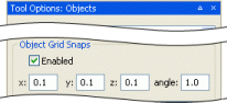
Object panel's Object Grid Snaps group box
If only one object is selected, then it will be rotated around itself. If more than one object is selected, then they will be rotated around their common centre.
If Terrain Import/Export toolbar buttonI —
— is selectedZooms the world map in and out, according to the direction of scroll.
If Project Tool toolbar buttonG —
— is
selectedZooms the world map in and out, according to the direction of scroll.
A — For details, see Toolbar.
B — For details, see Object panel.
C — For details, see Terrain Texturing panel.
D — For details, see Terrain Height panel.
E — For details, see Terrain Filtering panel.
F — For details, see Terrain Mesh Cut/Repair panel.
G — For details, see Project panel.
H — For details, see Keyboard shortcuts.
I — For details, see Terrain Import/Export panel.
J — For details, see BigWorld Messages panel.
Accessed via the File → Open Space menu item (for details, see Menu items), this dialog box allows you to choose the space to load in World Editor.
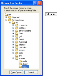
Browse For Folder dialog box
The list below describes the fields on this dialog box:
Folder list
Lists of sub-folders available in the resources folder.
Automatically invoked by World Editor when user chooses to perform an action that would otherwise discard unsaved changes (such as closing the application or changing space), it allows the user to specify how to handle these changes before proceeding.
The following actions will have World Editor invoke this dialog box in case there are unsaved changes:
Creating a new space (via the File → New Space menu item)
Opening an existing space (via the File → Open Space menu item)
Reloading all chunks in current space (via the File → Reload All Chunks menu item or the Ctrl+K keyboard shortcut)
Closing the application (via the File → Exit menu item, the window button, or any keyboard shortcut)
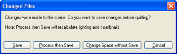
Changed Files dialog box
The list below describes the fields on this dialog box:
Save
Saves changes to the world — without calculating shadow, lighting, thumbnail, or ecotype information —, before proceeding with operation.
Process then save
Recalculates shadow, lighting, thumbnail, or ecotype information, then saves changes to the world, before proceeding with operation.
Change space without save
Proceeds with operation without saving changes.
Cancel
Closes the dialog box without performing any action.
Accessed via the File → Convert Space menu item (for details, see Menu items), this dialog box allows you to convert the current simple terrain space to one with terrain advanced features.
Note
A Simple Terrain is one created with BigWorld Technology 1.8 or earlier, or one created by selecting the File → New Space menu item, then clearing the New Space dialog box's Use Simple Terrain check box (for details, see New Space dialog box).
Simple Terrain has the following characteristics/limitations:
Fixed resolution of 25x25 height poles.
Only up to 4 texture layers.
No texture LOD.
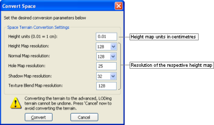
Convert Space dialog box
The fields in this dialog box have the same description as the New Space dialog box's Space Terrain Creation Settings group box (for details, see New Space dialog box).
Convert
Converts the current space to one with terrain advanced features specified in the dialog box.
For details on the converted files, see the document Client Programming Guide's section Chunks → Implementation files.
Cancel
Closes the dialog box without performing any action.
Accessed via the File → New Space menu item (for details, see Menu items), this dialog box allows you to create a new — blank — space according to the settings specified in it.
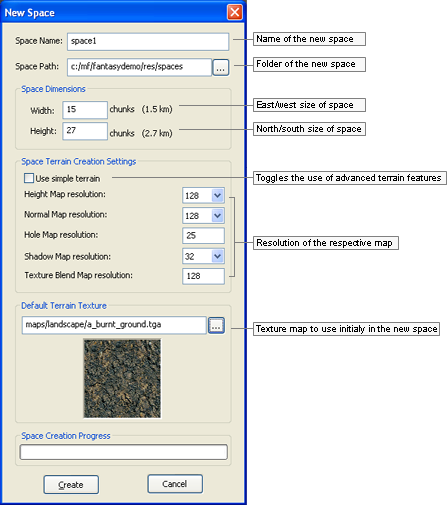
New Space dialog box
The list below describes the fields on this dialog box:
Space name
Name of the space to create.
Space path
Parent folder of the space to create. The Browse button (
 ) opens the New Space
Folder dialog box (for details, see New Space Folder dialog box).
) opens the New Space
Folder dialog box (for details, see New Space Folder dialog box).Space dimensions
Width, Height
Number of chunks in the space, in the east/west and north/south direction, respectively.
Space terrain creation settings
Use simple terrain
Determines whether to use terrain advanced features in the creation of the new space.
If this check box is cleared, then the remaining fields in the group box are disabled and the terrain will have the following characteristics:
Fixed resolution of 25x25 height poles.
Only up to 4 texture layers.
No texture LOD.
Height map resolution
Resolution of the height map per chunk.
Higher values in this field result in a more detailed terrain geometry, but also in higher rendering times.
Recommended value is 128.
Normal map resolution
Resolution of the normal map per chunk — this map contains information about the slope of the terrain, and is used for illumination.
Hole map resolution
Resolution of the holes map per chunk — this map contains information about the holes in the terrain, which are needed to transition between the terrain and an indoor chunk (shell).
Shadow map resolution
Resolution of the terrain shadow map per chunk — this map contains shadow information originated from objects (e.g., a house, which casts a shadow in the terrain) and from the terrain itself (e.g., a hill in the terrain, which casts a shadow onto itself).
Higher values in this field result in a longer time for shadow generation for the terrain.
Recommended value is 32.
Texture blend map resolution
Resolution of the texture layers blend maps per chunk — this map contains a blend information similar to an opacity/alpha channel on how to blend the textures onto the terrain.
Higher values in this fields allow for a more detailed terrain texturing, but also result in higher memory use.
Recommended value is 128.
Default terrain texture
Texture map to initially use for the terrain in the new space.
Create
Creates space under the folder specified in Space Path.
For details on the created files, see the document Client Programming Guide's section Chunks → Implementation files.
Cancel
Closes the dialog box without performing any action.
Accessed via the Browser button () in the New
Space dialog box's Space
Folder field (for details, see New Space dialog box), this dialog box allows you to
create a folder for the new space, or choose an existing one.
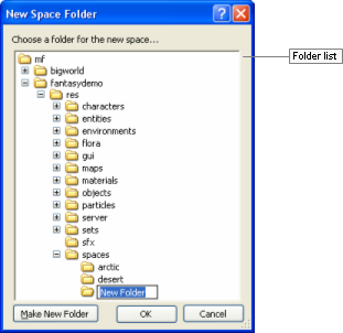
New Space Folder dialog box
The list below describes the fields on this dialog box:
Folder list
Lists the sub-folders available in the resources folder.
Make new folder
Creates a new folder under the one currently selected in Folder List.
Invoked by the Terrain Texturing panel's Noise group box's Noise Setup button (for details, see Terrain Texturing panel), this dialog box lets you configure the noise mask to be used in that panel.
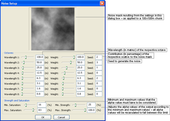
Noise Setup dialog box
The list below describes the fields on this dialog box:
Octaves
Wavelength
Length (in metres) of the respective octave.
Weight
Contribution (in percentage) of the respective octave in the noise mask.
Seed
Seed to generate the noise.
Strength and saturation
Min Saturation
Minimum value that the alpha value must have to be used in the noise mask.
Max Saturation
Maximum value that the alpha value might have to be used in the noise mask.
Min Strength
Minimum value that the output alpha value will have — all alpha values will be recalculated to fit between Min Strength and Max Strength.
Min Strength
Maximum value that the output alpha value will have — all alpha values will be recalculated to fit between Min Strength and Max Strength.
Invoked by the Object panel's Placement Method drop-down list box (for details, see Object panel) when the value (Edit Presets…) is selected, this dialog box allows you to create a group of settings that determine the values between which to randomise the orientation and size during the placement of objects.
This allows the creation of worlds with greater variety, but with less work by the builder.
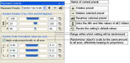
Placement Controls dialog box
The list below describes the fields on this dialog box:
Placement presets
Name of current preset.

Opens the Placement Preset Name dialog box, where the user can specify the name of a new preset.
Once the name is specified, all rotation and scale fields are set to their default values.
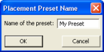
Placement Preset Name dialog box

Opens the Placement Controls dialog box, where the user is prompted to confirm the deletion.
After deleting the preset, Placement Presets drop-down list box is set to (Normal Placement).
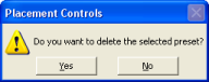
Placement Controls deletion confirmation dialog box

Opens the Placement Preset Name dialog box, where the user can change the name of the preset.
Random rotation
Group of fields determining the range of values within which the object's rotation (yaw, pitch, and roll) should be randomised.

Links the Y, P, and R values to each other, for both Min and Max.
This means that when Min or Max value of a rotation component is changed, the others are automatically changed as well.
Y
Min and Max values for yaw randomisation during object placement.
P
Min and Max values for pitch randomisation during object placement.
R
Min and Max values for roll randomisation during object placement.

Resets Min and Max values of the respective rotation component to its default value.
Random scale
Group of fields determining the range of values within which the object's scale (in x-, y-, and z-axes) should be randomised.
Apply scale proportionally on all axes
Randomises object's scale by the same amount in all axes, effectively keeping its proportion.
The
toggle button is automatically selected
when this option is selected, and cannot be cleared.Links the X, Y and Z values to each other, for both Min and Max.
This means that when Min or Max value of a scale component is changed, the others are automatically changed as well.
X
Min and Max values for scale randomisation along the x-axis.
Y
Min and Max values for scale randomisation along the y-axis.
Z
Min and Max values for scale randomisation along the z-axis.
Resets Min and Max values of the respective scale component to its default value.
Invoked by the Terrain Texturing panel's Imported group box's Browse button's Open dialog box (for details, see Terrain Texturing panel), this dialog box lets you select the file to be used as import mask in that panel.
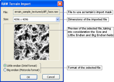
RAW Terrain Import dialog box
The list below describes the fields on this dialog box:
File
Path and name of the RAW file selected in the previous dialog box.
Size
Dimensions of the imported file — this is not necessarily the original size of the file, but rather the size that you want it to have as a mask.
Little endian (Intel format)
Determines whether the original mask was saved using the Intel format.
Big endian (Motorola format)
Determines whether the original mask was saved using the Motorola format.
Accessed via the File → Resize Terrain Texture Blends menu item (for details, see Menu items), this dialog box allows you to change the resolution of the texture layers blend map — this map contains a blend information similar to an opacity/alpha channel on how to blend the textures onto the terrain.
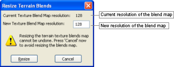
Resize Terrain Blends dialog box
The fields in this dialog box have the same description as the New Space dialog box's Space Terrain Creation Settings group box (for details, see New Space dialog box).
New texture blend map resolution
New resolution of the texture layers blend map.
Higher values in this fields allow for a more detailed terrain texturing, but also result in higher memory use.
Recommended value is 128.
Resize
Resizes the current texture layers blend map to the specified resolution.
Cancel
Closes the dialog box without performing any action.
Accessed by the button in various sliders, this dialog box allows
you to specify the minimum and maximum values for the slider that
invoked it.
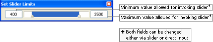
Set Slider Limits dialog box
Accessed via the Help → Shortcuts menu item (for details, see Menu items), the World Editor Shortcuts dialog box displays a list of shortcuts available on World Editor. For details on the complete list, see Keyboard shortcuts.
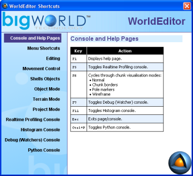
World Editor Shortcuts dialog box
BigWorld offers different ways to visualise the chunks in the scene, so that the world builder can choose the one most suitable for the task at hand.
The visualisation modes are switched by pressing F6 (for details, see Function keys), and are described below:
Normal
Displays the terrain as it will be rendered in the scene — no overlay is applied on the interface.
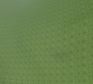
Normal mode
Chunk borders
Overlays a continuous white line around the border of the chunk over which the mouse is positioned.
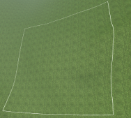
Chunk Borders mode
Pole markers
Divides the chunk over which the mouse is, and overlays pole markers icons on the corner of each one.
Pole Markers mode
Wireframe
Divides the chunk over which the mouse is, and overlays the wireframe grid indicator over each one.
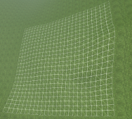
Wireframe mode
Assets used to populate the world are accessed via the Asset Browser. For details, see Asset Browser panel.
Note
Selected objects are indicated by white corners on their bounding boxes.
Selectable object s are indicated by rendering their bounding boxes in green when the mouse hovers over them — the objects that can be currently selected are specified by the Object panel's Selection Filter drop-down list box (for details, see Object panel).
Objects that could not be loaded are indicated by a red box and a message in the BigWorld Messages panel — to view this kind of message, the BigWorld Messages panel's Assets check box must be selected (for details, see BigWorld Messages panel).
This node gives access to all exported .model files. Models refer to the basic props that can be placed in the world.
Note
For more information on models, see:
document Client Programming Guide's section Models.
document Content Creation Manual's lessons (the document is accessed by pressing F1 or by selecting the Help → Content Creation menu item — for details, see Menu items):
Modify a Model in Model Editor
Add Models to the World
Best Practices → Animation tree — Using LOD models to share animations
For details on .model files' grammar, see the document File Grammar Guide's section .model.
Shells refer to the indoor chunks containing portals that you have exported to the shells folder.
A new indoor chunk is created by selecting a shell and placing it in the world. The new indoor chunk will contain all portals referenced in the shell.
Note
For more information on shells, see :
document Content Creation Manual's lessons (the document is accessed by pressing F1 or by selecting the Help → Content Creation menu item — for details, see Menu items):
Create an Internal Shell
Create an Internal Area in World Editor Using Shells
Add Lights to the World → Lighting Environments
Outdoor-to-Indoor Transitions → Placing an interior shell
This node gives access to all SpeedTree files (.spt) files.
Note
For more information on SpeedTree files, see:
The document Third-Party Integrations chapter SpeedTree.
document Content Creation Manual's lesson Best Practices → Using SpeedTree (the document is accessed by pressing F1 or by selecting the Help → Content Creation menu item — for details, see Menu items)
This node gives access to items previously saved as prefabs, so you can place them in the terrain.
Prefabs are elements such as objects, models, lights, shells, and items that are saved in World Editor via the Edit → Save Selection As Prefab menu item (for details, see Menu items).
They allow the artist to save a carefully arranged group of items to a single file, so that they can be used elsewhere in the world, without having to arrange the objects a second time.
Note
For more information on prefabs, see the document Content Creation Manual's lesson Create an Internal Area in World Editor Using Shells → Creating templates and prefabs (the document is accessed by pressing F1 or by selecting the Help → Content Creation menu item — for details, see Menu items).
Comprised of .py files, scripted entities are the dynamic components of a BigWorld game. World Editor can insert an entity placeholder into a chunk, so that your initialisation script (also called a personality script) can read it and create the entity as the chunk is loaded (via fetchEntitiesFromChunks — for details, see the Client C API's entry Class List → FetchFromChunksJob).
There are several placeholder models available in the bigworld/tools/worldeditor/resources/models folder.
For example, to create a new entity placeholder called Monster, follow the steps below:
Add new entry to
<res>/scripts/entities.xml.This is illustrated below:
<Monster/>
Create the file
<res>/scripts/entity_defs/Monster.def.A .def file is used to describe the properties and methods of the new entity (for details, see the document Server Programming Guide's section Directory Structure for Entity Scripting → The Entity Definition File).
An example entity definition file is illustrated below:
<root> <Properties> ... <my_property> <Type> INT8 </Type> <Flags> OTHER_CLIENTS </Flags>
<Default> 0 </Default>
<Persistent> true </Persistent>
<Editable> true </Editable>
<Flags> OTHER_CLIENTS </Flags>
<Default> 0 </Default>
<Persistent> true </Persistent>
<Editable> true </Editable>  ...
... For details, see Supported data types.
Must be set to true in order to make the property editable in World Editor.
Create the script file
<res>/scripts/editor/Monster.py.The function modelName specifies the model to represent the placeholder. Several models can be attached to one entity, which depends on the entity's attributes (for details, see fantasydemo/res/scripts/editor/Creature.py).
class Monster:
  def modelName( self, props ):
    return "helpers/props/standin.model"
World Editor directly supports only UINT/INT types, plus STRING and FLOAT (for details on the data types supported by BigWorld's game engine, see the document Server Programming Guide's section Properties → Property Types → Primitive Types).
You may create aliases for existing types by adding an entry to
<res>/scripts/entity_defs/alias.xml
(for details, see the document Server Programming Guide's section Properties
→ Property Types
→ Primitive Types).
Types supported by the game engine but not directly supported by World Editor are handled the following way:
World Editor uses Python's repr() function to get the string form of the data.
After using the data, World Editor uses the eval() function to convert the string representation back.
Therefore, data might be lost if for an object you have eval(repr(obj)) different from obj. Also, changes will be lost (object will retain its original value) if you set it to some illegal data.
Besides these types, you can also use ENUM types, in which case you must create a function to return a list of available enumeration values, as illustrated below:
def getEnums_<AttributeName>( self ):
The code excerpt below illustrates the use of enumeration by the Creature object in fantasydemo/res/scripts/editor/Creature.py:
class Creature:
  UNKNOWN      = 0
  STRIFF       = 1
  STRIFF_YOUNG = 2
  CHICKEN      = 3

  modelNames = {
    UNKNOWN:      None,
    STRIFF:       "characters/npc/striff/striff.model",
    STRIFF_YOUNG: "characters/npc/striff/striff_young.model",
    CHICKEN:      "characters/npc/chicken/chicken.model"
    }

  def modelName( self, props ):
    return Creature.modelNames[ props[ "creatureType" ] ]

  def getEnums_creatureType( self ):
    return ((Creature.STRIFF       , "Striff"       ),
           (Creature.STRIFF_YOUNG  , "Young Striff" ),
           (Creature.CHICKEN       , "Chicken"      ))

  def getEnums_creatureAge( self ):
    return (("Old"    , "Striff"       ),
           ("Young"   , "Young Striff" ),
           ("Evolved" , "Chicken"      ))
# Creature.py
fantasydemo/res/scripts/editor/Creature.py
This nodes gives access to user data objects that can be used to embed user defined data in Chunk files. User data objects are linkable objects which possess data that can be used by entities and scripts to achieve arbitrary tasks. User data objects can be placed in the world using World Editor, allowing users to edit their properties just like entities. The editor allows links to be added, edited, and deleted.
This section describes how to create the PatrolNode user data object as an example. These are the steps that were required to create the PatrolNode user data object type:
Add new entry to
<res>/scripts/user_data_object.xml<root> ... <PatrolNode /> ... </root>
Create the file
<res>/scripts/user_data_object_defs/PatrolNode.defA definition file is used to describe the properties and methods of the new user data object.
<root>
  <Domain> CELL </Domain>
  <Properties>
    <patrolLinks>
      <Type> ARRAY <of> UDO_REF </of> </Type>
      <Editable> true </Editable>
    </patrolLinks>
  </Properties>
</root>
For details on definition files, see the document Server Programming Guide's sections Directory Structure for User Data Object Scripting → The User Data Object Definition File.
Create script file
<res>/scripts/editor/PatrolNode.pyThere are several editor callback functions that can be implemented in the editor script
getEnum_<PROPERTY_NAME> - This can be used to define the possible values for this property displayed in the World Editor.
modelName - Used to define a custom model for this user data object type.
showAddGizmo - Guard function used to control the display of the add gizmo.
canLink - Guard function that checks if the user data object can link to the target object.
onDeleteObject - A callback function that gets called just before the user data object is deleted.
onStartLinkMenu - Returns the options that should appear in the custom context-sensitive menu for this user data object link.
onEndLinkMenu - Calls a command function based on the users choice in the context-sensitive menu.
postClone - A callback function that gets called just after the user data object is cloned.
User data objects can be found in the “User Data Objects” folder in the Asset Browser folder hierarchy. User data objects can be added to a space by click-dragging them from the asset browser into the space. When selected, user data object properties may have a link gizmo and/or a clone gizmo depending on their type.
Link Gizmo - Properties of type UDO_REF have a link gizmo. The link gizmo can be used to add a link to another user data object. If no link property is selected for the object, the first link property will be used to store the new link. If this property is a standard link property, the previous link will be discarded. If this property is a link array, the link will be added to the end of the array.
Clone Gizmo - Properties that are arrays of UDO_REF have a clone gizmo. The clone gizmo can be used to clone the current user data object. All properties are cloned except for the links, which are cleared. The postClone callback function allows scripters to decide how links behave using the clone gizmo, e.g. for PatrolNode objects, a link from the parent to the cloned node is created using this callback.
Selections of user data objects can be cloned using the <C> key. Linking information is retained when cloning selections of user data objects or when saving user data object prefabs.
Right-clicking on a user data object reveals its context-sensitive menu. In the first level the user data objects properties panel is selectable by default. If the user data object also has outgoing links, each property that has one or more links will also appear in this first level of the context-sensitive menu. When a property is selected, the second level of the context-sensitive menu is displayed. A single "Delete" operation is displayed is the link property is a standard link, or a single "Delete all" operation is displayed if the link property is an array of links.
Right-clicking on a user data object link reveals its context-sensitive menu. By default, the "Delete all" operation is selectable. This will delete all links between the two user data objects. Some user data object types (the user data object PatrolNode for example) make use of the optional python scriptable custom menu. This menu can contain type specific operations. Note that this menu is based on the type of the user data object, not on the type of the link property. Currently one of the user data objects is selected at random to perform the link operation, so the script operations should be commutative to the order in which the user data objects are given.
When there exists a link between two user data objects, but only one of the user data object is loaded, a chunk link extends out from the loaded user data object. This chunk link points to the centre of the chunk that contains the unloaded linked user data object. When performing link operations, the user data objects on either end of the link must be loaded. If one of the user data objects is not loaded, it will be force loaded.
When using a lock server, only some regions of the space will be editable. This has the following implications on what operations can be applied to user data objects:
Uneditable Regions - No operations can be applied to user data objects located in uneditable regions. These user data objects can not be moved, deleted, have changes made to their incoming or outgoing links, or have any of their properties changed.
Editable Regions - User data objects located in editable regions are either fully editable or partially editable.
Fully Editable - User data objects that only link to user data objects in editable regions are fully editable. These user data objects can be moved, deleted, have their properties changed, and have incoming and outgoing links added and removed.
Partially Editable - User data objects that link to user data objects in uneditable regions are only partially editable. These user data objects can not be deleted, can only move inside their current outside chunk, and cannot edit incoming or outgoing links to user data objects in uneditable regions. These user data objects can however add and remove links to user data objects in editable regions.
Both standard links and chunk links that extend across a lock boundary have a red tint to indicate that they are uneditable.
Increasing the number of user data objects in a space and increasing the distance travelled by their links increases the load placed on World Editor in a number of ways. In order to control the amount of work that will be performed at any one time a set of options have been exposed in World Editor’s options.xml, see the document File Grammar Guide's section → World Editor.
There is a cost associated with recalculating the geometry of a link so that it conforms to the terrain as chunks are loaded in. The user can control the size of the jobs as well as how often recalculation are performed by editing the last three variables above.
Chunk links do not have a context-sensitive menu because it would be of limited usefulness. Chunk links have a different kind of mapping than standard links, chunk links being one-to-many, while standard links are one-to-one. A single chunk link represents one or more property links to one or more user data objects in a particular outside chunk. As such the only useful operation would be to delete all links between the loaded user data object or entity, and all user data objects or entities in the unloaded chunk. It is unlikely that such an operation would be useful in practice. Another issue is regarding ambiguity among chunk links. If a user data object or entity has many chunk links, how is the user supposed to know which chunk link points to which chunk, and what user data objects or entities are being linked to. Therefore it was decided to avoid this feature.
The light settings allow you to create a variety of in-game lighting conditions, and to easily preview how they will look in the final game. You can light your models from a variety of directions and using different colours.
World Editor provides some light definition files in the bigworld/res/helpers/lights folder.
The kind of lighting to apply to the world is determined by General Options panel's Lighting group box (for details, see General Options panel).
Note
For more information on lights, see the document Content Creation Manual's lessons (the document is accessed by pressing F1 or by selecting the Help → Content Creation menu item — for details, see Menu items).
Add Lights to the World
Best Practices → Using the complete range of textures and lighting
Create an Internal Area in World Editor Using Shells → Creating templates and prefabs
Outdoor-to-Indoor Transitions → Placing an interior shell
For details on the grammar of light settings files, see the
document File Grammar Guide's section <light>.xml.
This node gives access to ambient particle systems created in Particle Editor (for details, see Particle Editor), so you can place them in your world.
Note that these particle systems must be time-triggered, otherwise you will not see any particles spawned.
Note
For more information on particles, see:
document Client Programming Guide's section Particles.
document Content Creation Manual's lessons ((the document is accessed by pressing F1 or by selecting the Help → Content Creation menu item — for details, see Menu items).
Manage Resources → Particles
Generate Particles for Special Effects
For details on the grammar of particle files, see the document
File Grammar Guide, section <particle>.xml.
This node gives access to texture images, used to paint the terrain.
Texture files can be dragged into Terrain Texturing panel's Texture In Chunk fields.
Note
For more information on textures, see:
document Content Creation Manual's lesson Create and Apply Terrain Texture Maps (the document is accessed by pressing F1 or by selecting the Help → Content Creation menu item — for details, see Menu items).
Terrain texture settings can be saved into
.brush files that can be later loaded from the
Asset Browser to help reduce the time needed to setup the many terrain
texturing options.
These files can be used in the Weather panel, in its Properties list, to allow for special weather effects for different weather systems.
Custom chunk items can be dragged from this folder into the 3D
world. BigWorld ships with one custom chunk item, water, represented by
the water.xml file.
The Asset Browser contains additional folders to aid in the creation of post-processing effects. These folders are:
Post-Processing Render Targets: Defined in Python in
bigworld\res\scripts\client\PostProcessing\RenderTargets\__init__.py.Post-Processing Effects: Defined in XML in the file
bigworld\tools\worldeditor\resources\post_processing_effects.xml. Each effect listed in the XML file corresponds to an Effect from the PostProcessing Python module, defined in the folderbigworld\res\scripts\client\PostProcessing\Effects.Post-Processing Phases: Defined in XML in the file
bigworld\tools\worldeditor\resources\post_processing_phases.xml. Phases are created through the Python scriptbigworld\res\scripts\client\PostProcessing\EditorPhases.py.Post-Processing FX Files: Lists
.fxfiles from the folderbigworld\res\shaders\post_processing.Post-Processing Textures: Lists texture files from the folder
bigworld\res\system\maps\post_processing.
For more information on the contents of these folders see Post-Processing panel.
Options for the tool modes and other elements are displayed in configurable panels. These panels contains most of the GUI for interacting with the editor.
The position and size of these panels can be changed directly by dragging the border and edges. They can be docked on any edge of the screen, or collapsed into shared panels. The customised layout is automatically saved for future sessions (for details, see Panel System.)
The descriptions in this section assume the World Editor's default layout — the default layout can be loaded via the View → Load Default Panel Layout menu item (for details. see Menu items).
The default layout consists of two main panels:
Tool Options panel, which displays the options for the current tool. These tools are:
Object panel — See Object panel.
Terrain Texturing panel — See Terrain Texturing panel.
Terrain Height panel — See Terrain Height panel.
Terrain Filtering panel — See Terrain Filtering panel.
Terrain Mesh Cut/Repair panel — See Terrain Mesh Cut/Repair panel.
Terrain Import/Export panel — See Terrain Import/Export panel.
Project panel — See Project panel.
Miscellaneous panel, with various tabs that are independent of current mode. They are:
Asset Browser panel — See Asset Browser panel.
Scene Browser panel — See Scene Browser panel.
Post-Processing panel — See Post-Processing panel.
Properties panel — See Properties panel.
Chunk Textures panel — See Chunk Textures panel.
General Options panel — See General Options panel.
Navigation panel — See Navigation panel.
Weather Preview panel — See Weather Preview panel.
Environment Options panel — See Environment Options panel.
Histogram panel — See Histogram panel.
BigWorld Messages panel — See BigWorld Messages panel.
The following sub-sections describe each panel, and the settings available on them.
This panel allows the user to configure overall options on how to handle objects, such as selection behaviour, reference coordinate system, snap mode, and placement randomisation settings.
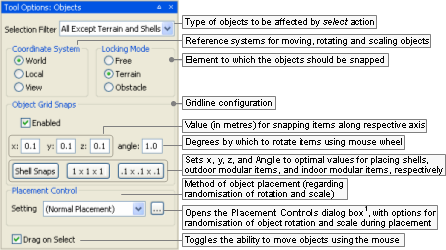
Object panel
1 — For details, see Placement Controls dialog box.
The list below describes the fields on this panel:
Selection filter
Sets the type of elements of the world that will be affected by a select action. This will affect selections made via the mouse (for details, see Mouse controls), the Edit → Select All menu item (for details, see Menu items), and the Ctrl+A keyboard shortcut (for details, see Keyboard shortcuts).
Also, as you move the mouse around the world, World Editor will display the bounding boxes only for selectable objects.
Coordinate system
Reference coordinate systems for moving, rotating and scaling objects.
World
Uses world coordinate system.
Local
Uses object coordinate system.
View
Uses camera coordinate system.
Locking mode
Element to which the objects should be snapped.
Free
Unlocks object movement — this is where the red, green, and blue direction axis can be used to drag the object along a single axis.
The height of the last placed object is used when placing new objects.
Note
Mouse cursor icon for this mode is a cross (
 ).
).Terrain
Sets object movement to slide along terrain.
This setting is ignored by the rotation gizmo (activated by pressing Shift — for details, see Keyboard shortcuts).
Note
Mouse cursor icon for this mode is a cross (
 ).
).Obstacle
Sets object movement to slide along obstacles, including terrain.
This setting causes the position gizmo to display a white sphere at its origin, which can be used to move the object along obstacles.
Please note that the snapping is applied only when there is exactly one item selected.
Note
Mouse cursor icon for this mode is a diamond (
 ).
).
Object grip snaps
Snap options for the snapping behaviour of objects.
Shell snapping is automatically enforced when placing a shell in the world, overriding all settings in this group box. However, you can modify the shell snap settings by editing bigworld/tools/worldeditor/options.xml's section shellSnaps. For details on this file's grammar, see the document File Grammar Guide's section → World Editor.
Enabled
Enables the snapping of objects, according to x, y, z, and Angle values.
x
Value (in metres) for snapping items along the x- axis.
y
Value (in metres) for snapping items along the y- axis.
z
Value (in metres) for snapping items along the z- axis.
Angle
Number of degrees by which to rotate the selected item using the mouse wheel (for details, see Mouse controls).
If only one item is selected, then it will be rotated around itself. If more than one item is selected, then they will be rotated around their common centre.
If the Enabled check box is cleared, then this value will be ignored, and selected object(s) will be rotated by 15˚.
Shell snaps
Sets x, y, z and Angle to the optimal values for placing shells.
1 x 1 x 1
Sets x, y, z and Angle to the optimal values for placing outdoor modular items.
.1 x .1 x .1
Sets x, y, z and Angle to the optimal values for placing indoor modular items.
Placement control
Method of object placement (regarding randomisation of rotation and scale).
Setting
Specifies how to place new objects in the world.
You can determine that objects should be placed as they are, or apply random rotation and/or scale. The latter is useful to give a natural look to the finished world, as each instance of the object will have orientation and size different from others.
The drop-down list box has the following options:
(Normal Placement)
Objects will be placed with their original size and orientation.
Preset list
Objects will be placed in the world with rotation and scale randomised according to values defined for the named preset in the Placement Controls dialog box (for details, see Placement Controls dialog box).

Opens the Placement Controls dialog box (for details, see Placement Controls dialog box), where you can specify ranges within which rotation and scale will be randomised during object placement.
Drag on select
Toggles the ability to move selected items via the mouse.
If turned off, objects can only be moved via the position gizmo.
Note
To distinguish from other modes, the brush is a purple dotted circle.

Terrain Texturing brush
Because this panel allow a great number of ways in which to interact with the terrain, the following sub-sections should also be consulted:
Terrain Texturing viewport context menu
This sub-section details the menu items available in the viewport's context menu (accessed by right-clicking an area in the viewport ).
Terrain Texturing keyboard shortcuts
This sub-section details the keyboard shortcuts that are unique to this mode.
.Terrain Texturing mouse controls
This sub-section details the mouse controls that are unique to this mode.
This sub-section details the gizmos that are unique to this mode.
For more details on using terrain textures, see the document Content Creation Manual's lesson Create and Apply Terrain Texture Maps.
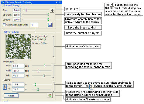
Terrain Texturing panel (top)
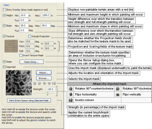
Terrain Texturing panel (bottom)
The list below describes the fields on this panel:
Size
Sets the size of the brush (in metres) used to paint the selected texture onto the terrain.
The [ (square left bracket) and ] (square right bracket) keysA decrease and increase the size of the brush, respectively.
Strength
Strength of the brush when blending texture onto terrain area underneath brush icon.
As you hold the left mouse button, the texture underneath the brush icon is gradually blended into the existing terrain texture. Small Strength values cause the blending to occur slowly, while the opposite happens for big Strength values.
Dragging the left mouse button blends the selected texture to the underlying terrain. Shift+[ (square left bracket) and Shift+] (square right bracket) keysA decrease and increase the strength of the brush, respectively.
Opacity
Maximum contribution of the Active Texture to the terrain under the cursor.
Save the brush to disk
This saves the brush settings to disk. The saved brush will appear in the Brushes section of the Asset Browser. The saved settings include the orientation and size of the brush, the texture used, the strength, the opacity, all of the the mask settings except the import mask.
Automatic layer limit
This limits the number of texture layers that terrain painting can create.
Active texture
Active texture's information
Displays a thumbnails of the active texture, alongside its filename, size, and memory footprint.
Projection
Group of fields configuring the projection that should be applied to the Active Texture when painting or replacing the texture in the terrain.
All fields in this group can be automatically updated by the texture projection tool (indicated by the
cursor icon — a red- and green-sided
square indicates the clicked area), which adjusts the Projection fields to that of the terrain
under the cursor.Yaw
Rotation about the y-axis to apply to the texture when painting or replacing the texture in the terrain.
Pitch
Rotation about the x-axis to apply to the texture when painting or replacing the texture in the terrain.
Roll
Rotation about the z-axis to apply to the texture when painting or replacing the texture in the terrain.
Scaling
Group of fields configuring the scaling to be applied to the Active Texture when painting or replacing the texture in the terrain.
U
Scale in the u-direction to apply to the texture when painting or replacing the texture in the terrain.
V
Scale in the v-direction to apply to the texture when painting or replacing the texture in the terrain.

Links the U and V fields, so that the texture is uniformly scaled.
Reset
Resets the Project and Scaling groups of fields to the Active Texture's original values.
Activates the edit projection mode, in which the texture projection/scale gizmo (for details, see Terrain Texturing gizmos) is displayed for the last-edited area.
Note
You can activate the texture projection/scale gizmo for a different area by clicking it while pressing Shift (for details, see Terrain Texturing keyboard shortcuts and .Terrain Texturing mouse controls).
Mask
Group of fields configuring how to apply the import mask to the terrain.
Show overlay
Determines whether non-paintable areas of the terrain (as determined by the import mask) should be rendered with a red tint.
Height

Determines whether the texture painting should be restricted to a height range.
Min
Minimum terrain height in which texture painting should occur.
Max
Maximum terrain height in which texture painting should occur.
Fuz
Height difference over which the transition between zero strength and full strength painting will occur.
This can be used to create fuzzy edges. If the value is set to 0, then painting around the Min or Max heights will result in a sharp edge.
Slope

Determines whether the texture painting should be restricted to a slope range.
Min
Minimum terrain slope in which texture painting should occur.
Max
Maximum terrain slope in which texture painting should occur.
Fuz
Slope difference over which the transition between zero strength and full strength painting will occur.
This can be used to create fuzzy edges. If the value is set to 0, then painting around the Min or Max slopes will result in a sharp edge.
Texture

Determines that the texture will only be painted over areas that match the texture mask settings, i.e. it will only paint over the texture mask's selected texture (or if it should exclude those areas, if the Invert Texture Mask check box is selected). This can be useful for replacing textures.
Include projection
Determines whether the projection of the terrain under the cursor should be matched for applying the mask.
Yaw, Pitch, Roll, U, V
Projection and Scaling fields that the texture underneath the cursor must have for the painting to be enabled (or disabled, if the Invert Texture Mask check box is selected).
Invert texture mask
Determines whether the texture mask should be used to specify the areas where texture painting will occur, or specify the areas where it will be excluded.
Noise

Determines whether the texture painting should use the specified noise mask.
Noise setup
Opens the Noise Setup dialog box (for details, see Noise Setup dialog box), where you can configure the noise mask.
Imported
Determines whether to use the import mask to paint the Active Texture onto the terrain.
Adjust
Allows you to adjust how to use the import mask, by doing the following:
Displaying a top view of the space, where you can relocate and resize the import mask.
Enabling the Browse button.
Enabling the
 ,
,  ,
,  ,
,  , and
, and  buttons.
Enabling the Strength field.
Browse
Opens the Open dialog box, where you specify the import mask, which can have the .r16, .raw, or .bmp extension.
If a RAW file is specified, then the RAW Terrain Import dialog box is displayed after clicking the Open button — for details, see RAW Terrain Import dialog box.
Rotates the import mask 90º counterclockwise.
Rotates the import mask 90º clockwise.
Flips the import mask horizontally.
Flips the import mask vertically.
Inverts the colours in the import mask.
Strength
Strength (in percentage) of the import mask.
Paint entire space using selected mask
Applies the current brush/mask combination to the entire space.
This is a quick way to paint, for example, snow peaks or rock faces.
Accessed by right-clicking the viewport while the Terrain Texture Tool toolbar button
() is selected, it contains the following
items:
Track cursorA
Determines whether the Chunk Textures panelB should be automatically updated with texture information on the chunk under the cursor.
Please note that this option will update the information on the Chunk Textures panel, but will not automatically activate it.
Manage texturesA
Displays/activates the Chunk Textures panelB, already updated with texture information on the chunk under the cursor (for details, see Chunk Textures panel).
Deselect chunkA
This menu item is only displayed if the Manage Textures menu item has been previously selected.
Deselects the chunk previously selected by the Manage Textures menu item, and which is currently displayed in the Chunk Textures panel.
Select texture for painting
List of textures under the mouse cursorC
Changes the active texture to the one selected in this sub-menu.D
Select texture and opacity for painting
List of textures under the mouse cursor (with Opacity in parenthesis)C
Changes the active texture to the one selected in this sub-menuD, and sets the Opacity field to the value displayed in parenthesis in this sub-menu.
Select texture for mask
List of textures under the mouse cursorC
This enables the Texture mask in the Terrain Textures panel and sets the mask texture to the one selected in this sub-menu. The Include Projection and Invert Texture Mask check boxes are turned off. Subsequent painting will replace any textures selected in the sub-menu with the Active Texture.
Select texture and projection for mask
List of textures under the mouse cursorC
This enables the Texture mask in the Terrain Textures panel and sets the mask texture to the one selected in this sub-menu. The Invert Texture Mask check box is turned off. The Include Projection check box is turned on and the Yaw, Pitch, Roll and U, V fields are set to match the yaw, pitch, roll, u and v-scale of the texture selected in the sub-menu. Subsequent painting will replace the texture mask texture with the Active Texture, but only for texture layers whose yaw, pitch, roll, u and v-scales match those of the texture selected in the sub-menu.
Edit projection and scale
List of textures under the mouse cursorC
Performs the same function as the
button on top of the Terrain Texturing panel
(i.e., it activates the edit
projection mode for the texture selected in this
sub-menuD, and
activates the texture projection/scale
gizmo — for details, see Terrain Texturing gizmos).
A — If the Manage Textures menu item is selected, then the chunk in which it was selected will remain as the current one in the Chunk Textures panelB, and the Track Cursor option will become temporarily inactive — to reactivate it, select the Deselect Chunk menu item.
B — For details, see Chunk Textures panel.
C — The textures in this sub-menu are listed from most solid to least solid.
D — The Active Texture field is automatically updated with the selected texture.
Please note that for completeness, the information provided in this section is also available in Keyboard shortcuts.
The list of World Editor's keyboard shortcuts can be displayed via the Help → Keyboard Shortcuts menu item (for details, see Menu items).
The list below describes the keyboard shortcuts that are unique to this mode:
Alt
Activates the texture sampler tool (indicated by the
cursor icon), which samples the dominant
texture of the chunk under the cursor — the Active Texture field will be updated
accordingly.Alt+Ctrl
Activates the texture/opacity sampler tool (indicated by the
cursor icon), which samples the dominant
texture of the chunk under the cursor and its opacity — the
Active Texture and Opacity fields will be updated
accordingly.Alt+Shift
Activates the texture projection tool (indicated by the
cursor icon — a red- and green-sided square
indicates the clicked area), which adjusts the Projection fields to that of the terrain
under the cursor.Shift
Activates the texture projection/scale gizmo (for details, see Terrain Texturing gizmos).
Please note that for completeness, the information provided in this section is also available in Mouse controls.
The list of World Editor's mouse controls can be displayed via the Help → Keyboard Shortcuts menu item (for details, see Menu items).
The list below describes the mouse controls that are unique to this mode:
Left button click
If Alt is pressed
Samples the dominant texture of the terrain under the cursor — the Active Texture field will be updated accordingly.
AltA activates the texture sampler tool (indicated by the
cursor icon).If Alt+Ctrl is pressed
Samples the dominant texture of the terrain under the cursor and its opacity — the Active Texture and Opacity fields will be updated accordingly.
Alt+CtrlA activates the texture/opacity sampler tool (indicated by the
cursor icon).If Alt+Shift is pressed
Adjusts the Projection fields to that of the terrain under the cursor.
Alt+ShiftA activates the texture projection tool (indicated by the
cursor icon — a red- and green-sided
square indicates the clicked area).
Left button drag
Draws the Active Texture into the terrain, according to the settings specified in the Terrain Texturing panel.
Right button click
Displays the Terrain Texturing panel's context menu (for details, see Terrain Texturing viewport context menu).
A — For details, see Terrain Texturing keyboard shortcuts.
Please note that for completeness, the information provided in this section is also available in Gizmos.
Texture projection/scale gizmo
Activated by pressing Shift while the Terrain Texture toolbar button —
— (for details, see Toolbar) is selected, or by clicking the
Terrain Texturing panel's
button, this gizmo contains the following
elements (each updating a different field in the panel):Projection gizmo (composed of red, green, and blue circles).
Red circle — updates the Roll field.
Green circle — updates the Pitch field.
Blue circle — updates the Yaw field.
Scale gizmo (composed of red and green cubes and a red- and green-sided rectangle or grid).
Red cube — updates the V field.
Green cube — updates the U field.
Texture projection/scale gizmo
This panel contains the options for the Terrain Height tool.
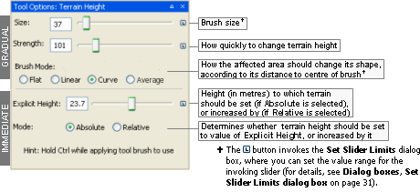
Terrain Height panel
Note
To distinguish from other modes, the brush is a green dotted circle. The brush for explicit height mode (activated by Ctrl) is a green square.

Terrain Height brush

Terrain Explicit Height brush
There are two basic modes of operation for the terrain brush:
Normal use (settings specified on top half of panel)
To gradually increase the height of the terrain, drag over the desired area while holding the left mouse button. To decrease the height, perform the same operation while pressing the middle mouse button (for details, see Mouse controls). Brush strength sets how fast the terrain height will change.
You can use the Shift key to toggle between this tool and the Terrain Filtering tool, which is very useful to allow for quickly smoothing out the terrain as you paint the heights.
Explicit Height (activated by pressing Ctrl — for details, see Keyboard shortcuts).
Terrain can immediately have its height changed to a certain value (absolute explicit height mode) or by a certain value (relative explicit height mode).
To a certain height:
To immediately set the height of an area:
Set the Explicit Height field to the desired value.
Select the Absolute radio button.
Drag over the desired area while pressing Ctrl — the brush icon changes to a square, indicating the area that will be affected.
By a certain amount:
To gradually increase the height of an area:
Set the Explicit Height field to the desired value.
Select the Relative option button.
Drag over the desired area while pressing Ctrl — the brush icon changes to a circle, indicating the area that will be affected.
The list below describes the fields on this panel:
For gradual changes
Size
Sets the size of the brush (in metres) used to apply the specified height onto the terrain.
The brush size is used both for incremental height changes (when the area affected is indicated by a round brush icon), and absolute height changes (when the area affected is indicated by a square brush icon).
The [ (square left bracket) and ] (square right bracket) keysA decrease and increase the size of the brush, respectively.
Strength
Sets the strength of the brush when incrementally applying the specified height to the terrain area underneath the brush icon.
As you hold the left mouse button, the height is gradually incremented to the area indicated by the round brush icon. Small Strength values cause the height to be incremented slowly, while the opposite happens for big Strength values.
Alt+[ (square left bracket) and Alt+] (square right bracket) keysA decrease and increase the strength of the brush, respectively.
Brush mode
How affected terrain should change its shape.
Flat
Brush's strength does not fall off until it reaches its edge. This results in plateaus with sharp cliff transitions.
Linear
Brush's strength falls off linearly away from its centre. Useful for producing pointy triangular heights.
Curve
Brush's strength falls off gradually away from its centre. This produces more rounded, softer heights.
Average
This mode samples the terrain height at the cursor position and flattens the area around it to that height. This mode is particularly useful for creating roads, paths, terraces and other terrain features.
For immediate changes(activated by CtrlA key)
Explicit height
Number of metres by which to change affected terrain.
Mode
Determines whether terrain height should be set to Explicit Height, or incremented by it.
Absolute
Sets terrain height to Explicit Height when mouse is dragged over the area while CtrlA is pressed.
Relative
Increases terrain height by Explicit Height when mouse is dragged over the area while CtrlA is pressed.
A — For details, see Keyboard shortcuts.
Note
To distinguish from other modes, the brush is a cyan dotted circle.

Terrain Filtering brush
This panel contains options for the terrain filter brush. The brush applies filtering operations to the terrain height. Each filter is a convolution kernel of the type often found in image editing software.
Filters give you the ability to make adjustments to the terrain, with a mechanism similar to the height-sculpting tool.
The most commonly used filters are the smooth ones. They help smooth the terrain, and reduce the jagged polygon appearance of the terrain.
For more details on filters, see the document Content Creation Manual's lesson Sculpt Terrain → Adding refinement filters. (document is accessed by pressing F1 or by selecting the Help → Content Creation menu item — for details, see Menu items).
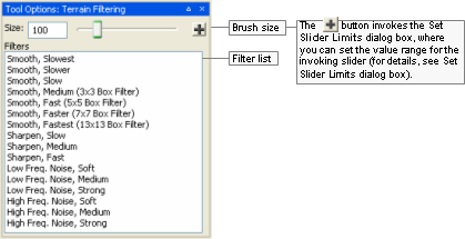
Terrain Filtering panel
The list below describes the fields on this panel:
Size
Sets the size of the brush (in metres) used to apply the chosen filter to the terrain area underneath the brush icon.
The [ (square left bracket) and ] (square right bracket) keysA decrease and increase the size of the brush, respectively.
Filter list
List of filters available for adjusting the terrain.
You can use the Shift key to toggle between this tool and the Terrain Height tool, which is very useful to allow for quickly smoothing out the terrain as you paint the heights.
A — For details, see Keyboard shortcuts.
Note
To distinguish from other modes, the brush is a green square.

Terrain Mesh Cut/Repair brush
This panel allows you to cut or repair holes in the terrain.
Holes in the terrain are especially useful for cutting out the area underneath shells so that the shell geometry does not z-fight with the terrain. It can also be used to cut entrances to underground shells.
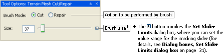
Terrain Mesh Cut/Repair panel
The list below describes the fields on this panel:
Brush mode
Action to be performed with the brush on the terrain underneath it.
Cut
Removes the terrain under the brush.
Repair
Restores the terrain under the brush.
You can also use the Shift key to toggle between Cut and Repair.
Size
Sets the size of the brush (in metres) used to apply the chosen filter to the terrain area underneath the brush icon.
The [ (square left bracket) and ] (square right bracket) keysA decrease and increase the size of the brush, respectively.
A — For details, see Keyboard shortcuts.
This panel allows the user to import terrain height data from other tools, such as PhotoShop and WorldMachine, and to tweak how it should be applied to selected area.
It also allows the user to export terrain height data of the selected area.
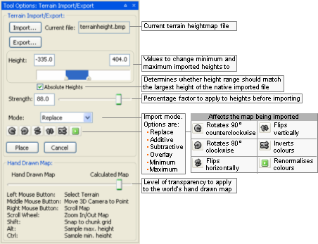
Terrain Import/Export panel
The list below describes the fields on this panel:
Import
Opens the Open dialog box, where you can specify the terrain height map file to be imported.
Accepted extensions are:
Greyscale heightmaps — .r16, .raw, .bmp
Terragen files — .ter
DTED2 files — .dt2
Current file
Terrain heightmap file to be imported.
Export
Opens the Save As dialog box, where you can specify the terrain heightmap file to which export height data about the selected area. Accepted extensions are:
Bitmap files (.bmp)
Raw files (.r16, .raw)
Terragen files (.ter)
Note
If you are planning to use WorldMachine to open the exported file, then please export it as a .raw, since WorldMachine cannot read .r16 files correctly.
Height
Minimum and maximum height of imported terrain.
Min, Max
Height of lowest and highest points in imported terrain map.
If the Absolute heights check box is selected, then all points in the imported map will have their heights adjusted to correspond to the Min and Max values.
When Current File is specified via the Import button, then Min is automatically set to 0.
Absolute heights
Determines whether the minimum and maximum heights in the imported file(s) should be adjusted to the values in the Height fields.
This field is especially useful when you want importing multiple files for areas next to one another. For example, suppose you have two RAW files that are to be placed next to one another — one with a mountain range and the other with a plain. If this check box is selected, and the Height field's Min value is set to the lowest point in the plain, and the Height field's Max value is set to the highest point in the mountains, then importing the two areas will result in terrain without seams. If this check box is cleared, then the maximum height of the plain will be the same as the maximum height of the mountains.
Strength
Percentage to apply to height in each point of map being imported when calculating result.
Mode
Terrain import mode.
Contains the following options:
Replace
Replaces the current terrain with the one being imported.
Additive
For each point in terrain, height is added to the one in map being imported.
Subtractive
For each point in terrain, height is subtracted from the one in map being imported.
Overlay
Finds the median height in map being imported. Then, considering this median height as being 0 metres high, applies the Additive mode.
Minimum
For each point in terrain, height is set to the one in map being imported, if it is lower than the one in current map.
Maximum
For each point in terrain, height is set to the one in map being imported, if it is higher than the one in current map.
Map buttons
Affect the map being imported.

Rotates map 90° counter-clockwise.

Rotates map 90° clockwise.

Flips map horizontally.

Flips map vertically.

Inverts colours in map.

Renormalises colours in map, to reflect changes to Height.
If minimum and maximum heights are changed via the Height field, the colours of map being imported will be out-of-date, until this button is clicked.
Place
Imports the selected map.
Cancel
Cancels the import.
Hand drawn map
Changes the level of transparency applied to the world's hand drawn map layer that is rendered over the world's game map.
This allows users to compare between the world as initially specified by the game designer (Hand Drawn Map), and the one implemented by the world builders (Calculated Map).
This panel gives you access to multi-user editing of the world, implemented by the Lock Server (for details, see Lock Server (BWLockD)).
It also allows you to quickly navigate through large worlds by clicking the desired area with the mouse's middle button or scroll wheel (for details on mouse controls while in Project View mode, see Mouse controls).
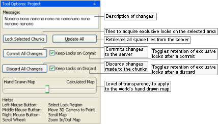
Project panel
The list below describes the fields on this panel:
Message
Description of the changes to the world.
Lock selected chunks
Tries to obtain an exclusive lock of the region selected on the map.
Locking a selection is useful for multi-user editing of the world, as it prevents two people from working in the same area.
For details, see Locking an area.
Update all
Reads all space files from the server and updates the world.
Commit all changes
Writes to the repository all changes made to the world.
After committing, other users will be able to see your changes.
Keep locks on commit
Toggles the retention of exclusive locks after committing your changes.
Discard all changes
Rejects the changes you made to the world, overwriting them with current version.
Keep locks on discard
Toggles the retention of exclusive locks after discarding your changes.
Hand drawn map vs. Calculated map
Changes the level of transparency applied to the world's hand drawn map layer that is rendered over the world's game map.
This allows users to compare between the world as initially specified by the game designer (Hand Drawn Map), and the one implemented by the world builders (Calculated Map).
This panel gives access to assets through the Asset Browser, an interface that is available in World Editor, Model Editor, and Particle Editor. For details, see Asset Browser.
It also allows you to choose how objects should be placed in the world.
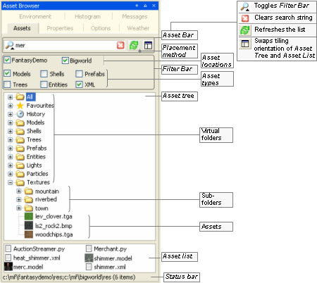
Asset Browser panel
The list below describes the fields on this panel:
UAL fields
For details, see Asset Browser.
The interaction between the different BigWorld asset types and World Editor via the Asset Browser is described in the sections below.
To place an asset in the world:
Drag its thumbnail in the Asset List and drop it in the viewport.
— or —
Select its thumbnail in the Asset List, place the mouse pointer in the desired location in the world, then press Enter (for details, see Keyboard shortcuts).
Drag-and-drop operation is specific to the tool that implements it, and the type of asset being dragged, as described in the table below (asset types are listed in the order in which they appear in the Asset Tree):
| Asset type | Drop locationA | Effect |
|---|---|---|
| Models | 3D Viewport | Places the dragged asset in the space. |
| Shells | ||
| Trees | ||
| Prefabs | ||
| Entities | ||
| User Data Objects | ||
| Lights | ||
| Particles | ||
| Misc | ||
| Textures | Terrain Texturing panel's Active Texture or Mask Texture fields. | If dropped onto the Active Texture then the texture becomes the texture used when painting. If dropped onto the Mask Texture then the texture becomes the texture replace when painting. |
| Brushes | Terrain Texturing panel. | Changes the current terrain painting brush to the one in the brush file. |
| Post-Processing Effects | Post-Processing panel's graph view | Adds the Effect and its phases into the post-processing chain at the drop position. |
| Post-Processing Phases | Post-Processing panel's graph view | Adds the Phase into a post-processing Effect in the chain at the drop position. |
| Post-Processing Textures | Post-Processing panel's graph view or properties | If dragged on top of a Phase node in the graph view, a popup appears showing the texture properties for the Phase, and you can drop the texture onto one of these properties. It can also be dropped over a texture property of the selected Phase in the properties area. |
| Post-Processing Render Targets | Post-Processing panel's graph view or properties | If dragged on top of a Phase node in the graph view, a popup appears showing the render target and texture properties for the Phase, and you can drop the render target onto one of these properties. It can also be dropped over a render target or texture property of the selected Phase in the properties area. |
| Post-Processing FX Files | Post-Processing panel's graph view or properties | If dragged on top of a Phase node in the graph view, a popup appears showing the FX properties for the Phase, and you can drop the FX file onto one of these properties. It can also be dropped over an FX property of the selected Phase in the properties area. |
Drag-and-drop operation in World Editor's Asset Browser panel
A — If the asset file is dropped in the Favourites special virtual folder, then it is added to that folder. For details, see Asset file.
Defined in Asset Browser's configuration file (for details, see Customisation), virtual folders list files of a specific asset type.
For details on the listed asset types, see Assets.
This panel provides functionality for easy listing, searching, selecting and managing of the objects that are currently loaded in the space. This panel provides the following features:
Browse the list of objects currently loaded in the space, sorted by any column or property.
View the list of objects in collapsible groups, grouped by chunk, asset type, file path, number of triangles, number of primitive calls, etc.
Easily select objects in the space by selecting items in the Scene Browser list.
Search for objects in the space, by searching in some or all properties of the objects, using multiple keywords and/or DOS-style wild cards.
Zoom to an object from the list.
Configure which columns or properties to view, and save different configurations as presets.
Hide or Unhide objects in the space, one by one, to improve editing of complex spaces.
Freeze or Unfreeze objects in the space, one by one, to avoid modifying objects accidentally.
Toggle boolean properties of one item or the whole selection with a single click. For example, it allows to change properties such as "casts shadow" and "reflection visible", or the hidden or frozen state, with a single click.
More details follow each of the screen shots below.
Browsing and Selecting:
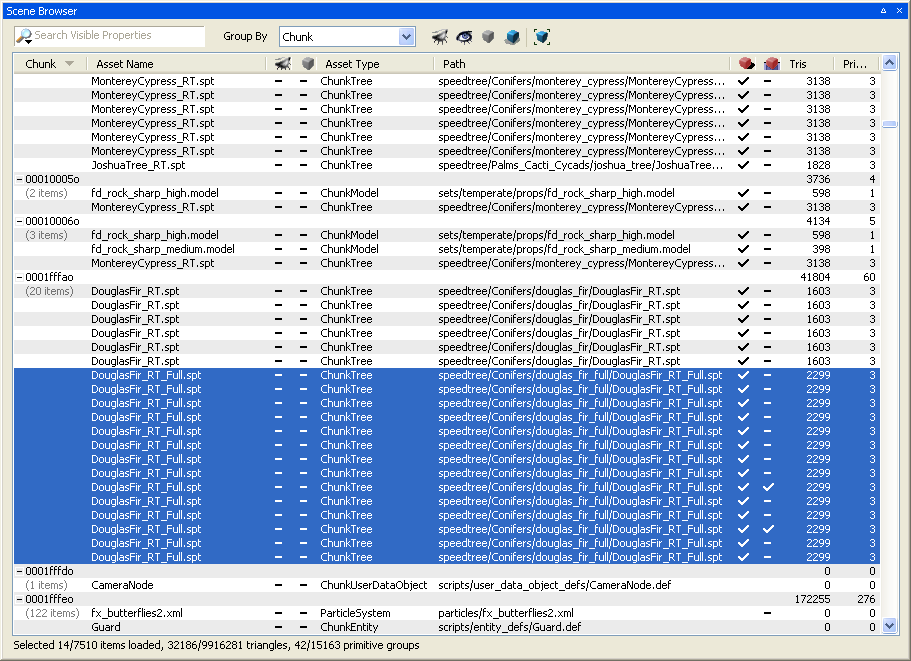
Scene Browser Panel - Selecting Objects
This screen shot shows the elements of the Scene Browser panel. On the top of the panel we see the search field, the grouping drop-down list, and the tool bar, taking most of the panel's area is the object list, and at the bottom is the status bar. The tool bar includes buttons to hide, unhide, freeze, unfreeze and auto-zoom to object:
Hide / Unhide: Allow temporarily hiding objects in order to simplify editing of complex scenes. Hidden objects cannot be selected or seen in the 3D view, but they can be seen in the Scene Browser. The hidden state is an editor-only state, and will not have any effect on the client engine or the server.
Freeze / Unfreeze: Allow temporarily freezing objects to avoid accidentally modifying it. Frozen objects cannot be selected or modified in the 3D view, but they can be selected in the Scene Browser. The frozen state is an editor-only state, and will not have any effect on the client engine or the server.
Auto-zoom: When enabled, it will zoom to an object as soon as it is selected in the Scene Browser list. When disabled, the user can still zoom to objects by double-clicking or right-clicking on the list.
Selections can be made using the standard selection keys and click combinations, such as Ctrl + click to add/remove to the selection, Shift + click to select a range of items, and so on. Because the Scene Browser supports searching and sorting, it makes it the ideal as an alternative view for selecting items. The screen shot shows the objects grouped by chunk. The search and grouping functionalities will be discussed next.
Searching:
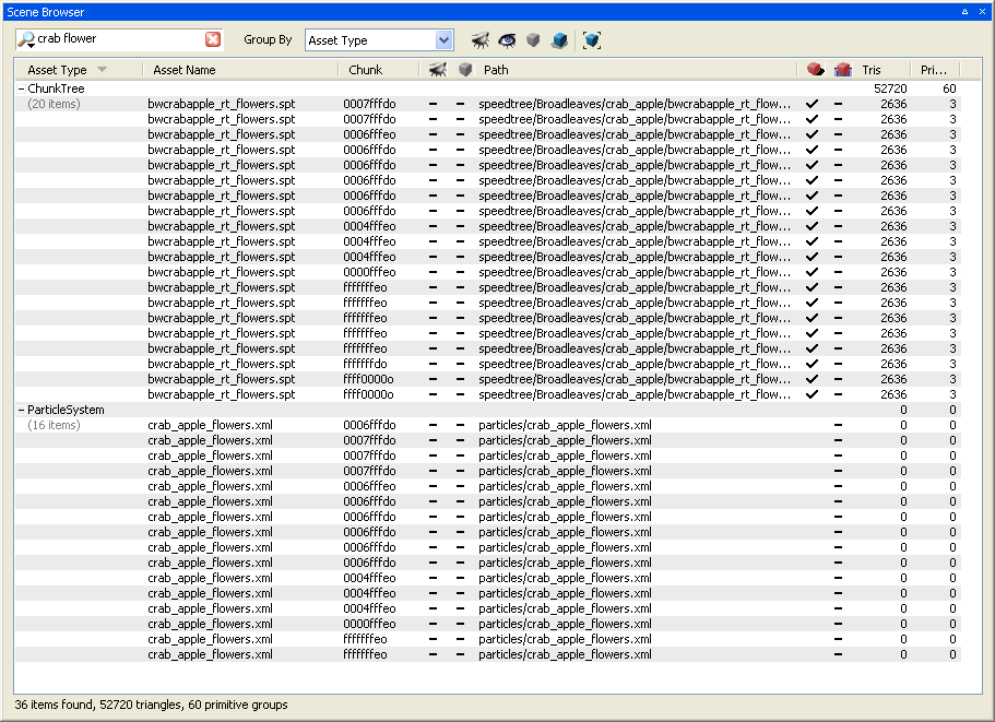
Scene Browser Panel - Searching
In this screen shot, the keywords "crab" and "flower" have been typed into the search field in the top-left of the panel. The search results are quickly shown down in the list, and when specifying multiple keywords, separated by a space, the Scene Browser searches for objects that match all the keywords in the field. Additionally, it is possible to use DOS-style wild cards, using the wild card characters "*" and "?". The search is matched against one or more of the object properties, depending on the search filter selected (see the next screen shot).
Search Filters:
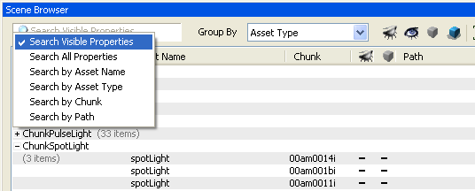
Scene Browser Panel - Search Filters
By clicking on the magnifying glass icon, the user can select one of the different search options, to search in the visible properties only, in all properties, or in one of the built-in common properties.
Grouping:
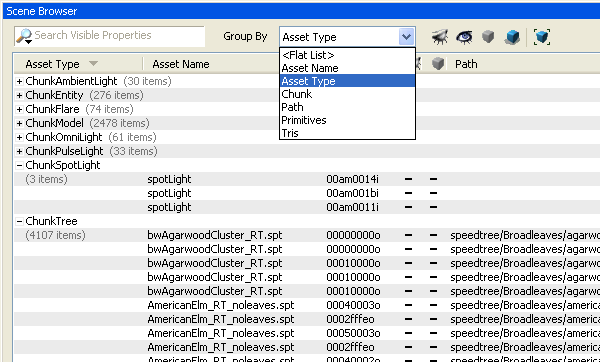
Scene Browser Panel - Grouping
The list can be viewed as a flat list, sorted by any column or property, or it can be viewed with objects grouped by one of the grouping criteria provided in the "Group By" drop-down list. In the screen shot, the list is being grouped by "Asset Type". Groups can be collapsed or expanded, and show some basic statistics for the group, such as the number of items in the group, the number of triangles used by the group, and the number of primitive calls.
Columns:
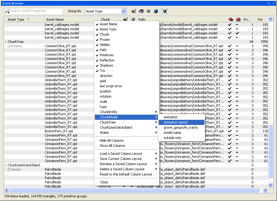
Scene Browser Panel - Column Visibility
At the top of the list is a header containing the column names for the properties being shown in the list. These columns are generated from the object properties. Right-clicking on the column header displays the columns menu. This menu allows for showing only the columns that are of interest to the user. The common columns are listed first, then the asset type specific columns below it. After editing the column visibility, the user can just click outside the menu, or click the "Close" menu item at the bottom to close it.
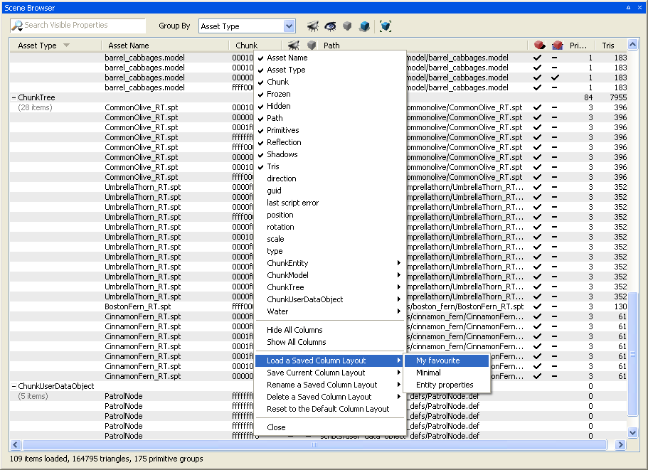
Scene Browser Panel - Column Layouts
It is also possible to save and load column layouts In the columns menu. The user can load a previously saved layout, save the current layout to a new layout file, save the current layout on top of a preexisting layout, rename or delete previously saved layouts, or simply reset the current layout to the default layout. This allows the user to have different sets of columns depending on the kind of world building he or she is doing.
Context Menus:
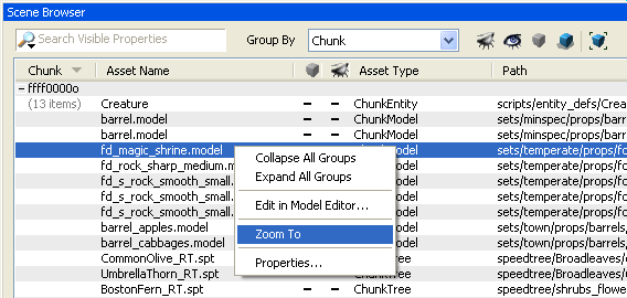
Scene Browser Panel - List Context Menu
A context menu is also displayed when right-clicking on an object, displaying the same menu items as the context menu of the 3D view, but with the additional option to zoom to the item in the 3D view. Also, it displays menu items to collapse or expand all groups.
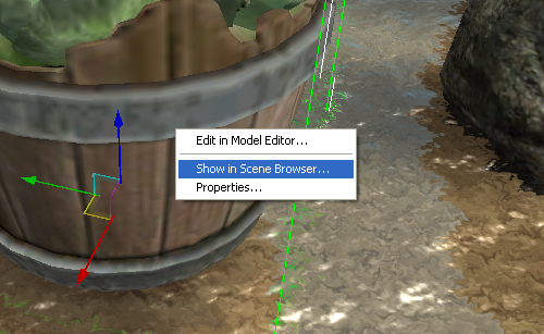
Scene Browser Panel - 3D View Context Menu
In the 3D view, an additional option has also been added to the context menu which allows finding the selected object inside the Scene Browser's list.
Additional Notes:
The Scene Browser works on the currently loaded objects only. The number of objects loaded depends on how far the far plane is set, but it's important to keep in mind that a large value for the far plane will require too much memory, depending on the complexity of the space.
There can be a delay from when an object is loaded, unloaded, or one of its properties is modified, and when the Scene Browser list reflects the change. This is by design, to keep the performance of the application as unaffected by the Scene Browser as possible.
This panel allows creating, editing and previewing post-processing effects that can be later used in the game.
The panel itself is divided in three main areas, as shown in the following image:
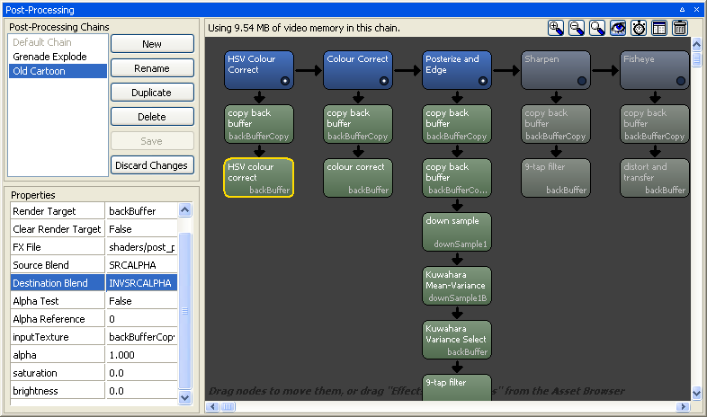
Post-Processing Panel - The Three Main Areas
Post-Processing Chains Area:
Contains the list of available post-processing chains and buttons for performing actions specific to post-processing chains editing.
In the chains list, there is a special item representing the system chain, called the Default Chain. When this chain is selected, it allows other subsystems to modify the post-processing chain as they would in the game. For example, changing the Post-Processing graphics setting in the Options panel will set a completely different chain depending on the setting chosen, and changing the weather in the Weather panel will make slight modifications to the system chain to better represent the weather selected.
The action buttons are, from top to bottom:
New: Creates a new chain.
Rename: Renames the currently selected chain.
Duplicate: Copies the currently selected chain into a new chain.
Delete: Deletes the selected chain
Save: Saves changes made to the currently selected chain.
Discard Changes: Brings the chain back to how it was before being modified.
By default, chains are saved as .ppchain
files into the
bigworld\res\system\post_processing\chains folder.
If necessary, the chains folder can be changed by adding the tag
<chainsFolder> inside a
<post_processing> tag, containing the desired
path, in World Editor's options.xml file.
Graph view and Tool bar Area:
At the top of this area is a small tool bar that contains summary
information about the current chain and three action buttons. The three
zoom buttons  allow for zooming in, zooming out, and going back
to the default zoom respectively. The Preview button
allow for zooming in, zooming out, and going back
to the default zoom respectively. The Preview button  toggles previewing of each Phase's result
in-place. The Profiling button
toggles previewing of each Phase's result
in-place. The Profiling button  toggles measuring the time spent by the
post-processing chain in the GPU. Important:
Please note that World Editor's performance will decrease when
using the Preview or Profiling modes. The Layout button
toggles measuring the time spent by the
post-processing chain in the GPU. Important:
Please note that World Editor's performance will decrease when
using the Preview or Profiling modes. The Layout button
 cycles through the different area arrangements
available, to help improve the panel's usability depending on the
panel's proportions. The Delete All button
cycles through the different area arrangements
available, to help improve the panel's usability depending on the
panel's proportions. The Delete All button  removes all the Effects and Phases from the
current chain (will ask for confirmation first).
removes all the Effects and Phases from the
current chain (will ask for confirmation first).
Bellow the tool bar is the chain graph view, which shows the different stages in the current post-processing chain in a graphic way. Each stage is called an Effect (blue nodes), and each Effect can contain stages, each called a Phase (green nodes). The post-processing engine will execute each Phase from each Effect, going from top to bottom and from left to right.
These are the ways you can interact with the graph view:
Selected an Effect or Phase: Click on an Effect or Phase to select it, showing its properties in the Properties area.
Pan: If you press the left mouse button on the background of the view and hold it down, you can move the mouse to pan the nodes in the view. You can also press space before pressing the mouse down on top of a node to pan, which is useful when the view is too small and doesn't have background areas in view.
Zoom In/Out: Use the mouse wheel to zoom in or out into the view, making the nodes bigger. This is particularly useful when in Preview mode
.Delete an Effect or Phase: When the mouse cursor is positioned on top of an Effect or Phase, a red close button appears in the top right corner of the node. Click it to delete the Effect or Phase.
Enable or Disable an Effect: You can click the button on the bottom right corner of the Effect node
 to enable or disable that Effect in the
chain. Having an Effect disabled might make sense, for example, if
that effect will be turned on by script in the game (a grenade
explosion, a particular bloom effect, etc).
to enable or disable that Effect in the
chain. Having an Effect disabled might make sense, for example, if
that effect will be turned on by script in the game (a grenade
explosion, a particular bloom effect, etc).Rearrange Effects: Drag and drop can be used to change the order of Effects in the chain.
Rearrange Phases: Drag and drop can also be used to change the position of a Phase in an Effect, or to move the Phase into another Effect.
Add an Effect or Phase: It's possible to add a new Effect or a new Phase to an Effect by dragging the desired Effect or Phase from the Asset Browser's Post-Processing Effects or Post-Processing Phases folders respectively.
Clone an Effect or Phase: Drag and drop while holding the CTRL key.
Assign a Render Target, a Texture or an FX file to a Phase: Simply drag a render target, a texture or an fx file from the Asset Browser over a Phase. Before you release the mouse button, a pop-up menu appears displaying the Phase's properties that can receive the dragged asset.
Assign a Phase's output Render Target to another Phase: Simply drag the handle next to the Phase's output render target name on top of the desired destination Phase, and before you release the mouse button, a pop-up menu appears displaying the Phase's properties that can receive the render target.
Properties Area:
Allows editing the properties of the currently selected Effect or Phase in the graph view. Effects and Phases properties are discussed below:
Effect properties:
All Effects have only two properties, Effect Name and Bypass. The Effect Name is used only as a label in the editor, and won't necessarily affect its usage in the game. The Bypass property is a vector of four floats that determines if the Effect is enabled and if it should be applied during rendering or not. At the moment, this value is tied with the Bypass button on the bottom right corner of the node
, and only the alpha value is used (0 for
disabled or non 0 for enabled).Phase properties:
There are several different types of Phases, and each type has its own set of properties that can be defined in either Python or C++, but a few deserve special attention:
Render Target: Contains the name of the output render target for the Phase. This render target can be filled in by copy & paste from another Phase's Render Target field, or can be dragged from the Asset Browser's Post-Processing Render Targets folder. Render Targets are defined in script by the game programmers beforehand. A special render target identified as "backBuffer" represents the screen's back buffer.
Clear Render Target: If set to true, the output render target is cleared before applying the Phase's result. If set to false, the results are accumulated.
FX File: Some Phases have an associated DirectX .fx file which contains the shader code to perform the desired processing. The user can type it in, browse for it using a standard file open dialog, or can drag it from the Asset Browser's Post-Processing FX Files folder.
Source Blend and Destination Blend: Allows choosing the desired blending modes for the Phase.
inputTexture: Some phases contain one or more fields for textures and/or render targets to be used as inputs by the Phase's shader. In most cases, the user will want to use the previous Phase's Render Target output as the input texture for the Phase, but in general this field can be set to any Render Target or texture. For example, a clever post-processing chain will have a down sampling Effect which outputs to an internal render target, and this render target can then be used one or more times as input in Phases of other Effects (such as the Bloom in the default chain).
alpha, additionalAlpha: These field control how much of the Phase's processing is actually blended into the output render target. In some cases an Effect won't have any visible impact on the screen, even when the Bypass button is on, because the alpha value is 0.
Care has been taken into giving all properties sensible names and informative tool-tips, so they are self explanatory. It's also recommended that you study the system's default chain to understand better how specific Phase properties are set.
If custom Phases or Render Targets are needed in addition to the included ones, your client engine programmer will have to add them by editing the post-processing scripts. Once the artist has created a set of chains to be used in the game, the game programmer can load these chains when needed from the game engine. For more information, see the Client Programming Guide.
This panel allows you to edit the properties for the currently selected item or group of items (except for chunk properties). Note that this action will flag the current chunk as dirty.
The list of displayed properties depends on the item selected — for details, see Client Programming Guide's section 3D Engine (Moo) → EffectMaterial → Artist-editable/tweakable variables.
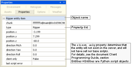
Example of an entity's properties
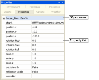
Example of a model's properties
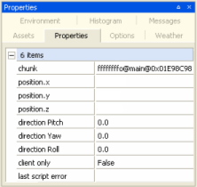
Common properties when multiple objects are selected
The list below describes some of the fields that appear on this panel:
Object name
Name of the selected object.
Property list
Animation
List of animations specified for the model in the .model file (for details on this file's grammar, see the document File Grammar Guide's section .model).
Value is set to the animation currently being played.
Animation speed
Speed of the animation being currently played.
Chunk
Chunk where the item is located.
Client only
Determines that the entity will not exist on the server, and will not have cell nor base scripts.
For details, see the document Client Programming Guide's section Entities → Entity scripts.
Colour
RGB colour of the selected item, in hexadecimal format.
Cone angle
Sets the angle of the cone of light generated by spot light.
The angle at which the light is placed in relation the ground or model affects its intensity.
Available only for spot lights.
Dynamic
Specifies that light should be applied to dynamic, i.e., moving objects.
Available only for directional lights, omni lights, and spot lights.
Direction pitch, Direction yaw, Direction roll
Pitch, yaw, and roll of direction of the light.
Available only for directional lights and spot lights.
Inner radius
Sets the area over which the light will be at full intensity.
Available only for omni lights and spot lights.
Model name
Model file (for details on this file's grammar, see the document File Grammar Guide's section .model).
Multiplier
Sets the multiplier for the RGB value of the colour.
The RGB values will be multiplied by the value set for this field, effectively making the item brighter.
Available only for lights.
Outer radius
Sets the total area influenced by light.
The area starting at Inner Radius will have light at full intensity, which will be faded away until it is completely off when it reaches Outer Radius.
Available only for omni lights and spot lights.
Outside only
Specifies whether the object can only be placed on outside chunks.
If an object placed in an inside chunk has this property set to true, then World Editor will move it to a suitable outside chunk.
This property is used in cases when a model is to be rendered from outdoors, and acts as a facade for an indoor shell. This prevents the model from being recognised as belonging to the indoor shell, and hence being lit as such.
The exterior of a house that surrounds an indoor shell is a good example of when this property would be used.
Position.x, Position.y, Position.z
Position of the item along the respective axis.
Rotation pitch, Rotation yaw, Rotation roll
Pitch, yaw, and roll of the item in its currently placement in the world.
Scale.x, Scale.y, Scale.z
Scale in which to draw the item along the respective axis.
Specular
Specifies that light should be applied to materials with a specular map specified.
Available only for directional lights, omni lights, and spot lights.
Static
Specifies that light should be applied to static, i.e., scene objects.
Available only for directional lights, omni lights, and spot lights.
Colour adjust
It contains the following fields:
Red,Green,Blue
Sets the red, green, and blue components of the colour, respectively.
Multiplier
Value to multiply colour's RGB value by.
This affects the overall luminosity of a light without affecting its hue.
Available only for omni lights and spot lights.
This panel allows you to check which textures are being used on a chunk, thus allowing you to better manage the existing texture layers painted onto it.
For more details on managing chunks' terrain textures, see the document Content Creation Manual's lesson Create and Apply Terrain Texture Maps.
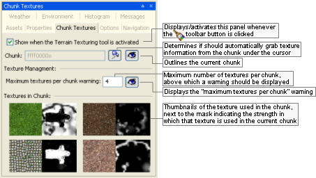
Chunk Textures panel
The list below describes the fields on this panel:
Show when the Terrain Texturing tool is activated
Determines whether this panel should be activated/displayed whenever the Terrain Texture Tool —
— toolbar button is clicked.Chunk
ID of the chunk which texture information is being displayed.
 /
/
Determines if World Editor should automatically display texture information from the chunk under the cursor.
 /
/
Determines if World Editor should outline the chunk under the cursor.
Texture management
Maximum textures per chunk warning
Number of textures per chunk above which a warning message should be displayed in the offending chunks.
The warning will be displayed in the chunk as illustrated in the image below.
 /
/
Determines whether World Editor should display the "maximum texture per chunk" warning.
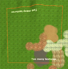
Example of a chunk displaying the "maximum textures per chunk" warning
Texture thumbnail/mask
Thumbnails of the texture used in the chunk under the cursor, next to the mask indicating the strength in which it is used.
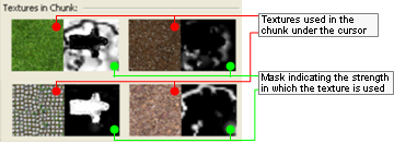
Texture thumbnail/mask information
The following keys can be used with this panel:
Left button click
Adds the texture under the mouse cursor to the selection.
Left button click + CTRL key
Toggles the texture under the mouse cursor into or out of the selection.
Space key
Merges the selected textures into the last texture selected. The last texture selected has a slightly thicker red rectangle around it.
Delete key
Deletes the selected textures. They are replaced by the texture that was not selected and contributes the most to the chunk.
Right button click
Displays the Chunk Textures panel's context menu as below.
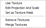
The Chunk Textures panel's context menu
The menu items are as follows:
Use Texture
Select the texture as the Active Texture on the Terrain Texturing panel.
Edit Projection and Scale
Activates the edit projection mode of the Terrain Texturing panel with the selected texture being the edited texture layer. See .Terrain Texturing mouse controls
Set as Texture Mask
Selects the texture as the texture mask on the Terrain Texturing panel.
Remove Texture(s)
Deletes the selected textures. They are replaced by the texture that was not selected and contributes the most to the chunk. This is the same as pressing the Delete key.
Merge Textures
Merges the selected textures into the last texture selected. The last texture selected has a slightly thicker red rectangle around it. This is the same as pressing the Space key.
This panel allows you to specify the scene elements that should be rendered in World Editor, and general settings such as far plane and the kind of lighting to render.
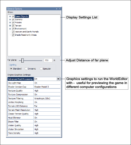
General Options panel
The list below describes the fields on this panel:
Show
Group of settings configuring the visibility of items in the world.
Game Objects
Toggles the rendering of Game Objects.
Entities
Toggles the rendering of Entities.
User Data Objects
Toggles the rendering of User Data Objects and the old patrol path graphs.
Scenery
Toggles the rendering of scenery items in the world.
Wireframe
Toggles the rendering of scenery items as wireframe.
Particles
Toggles the rendering of particle systems.
BSP
Toggles the rendering of objects' BSPs.
Particle system bounding boxes
Toggles the rendering of particle systems' bounding boxes.
Water
Toggles the rendering of water items (for details on water properties, see the document Content Creation Manual's lesson Add Water to the World).
Reflection,Simulation
Toggles the respective feature for all bodies of water in the world.
For an item to be reflected in a body of water and suffer refraction, its property reflection visible must be set to true in the Properties panel (for details, see Properties panel).
Shells
Toggles the rendering of shells in the world.
Game visibility
Toggles the use of the portal visibility algorithm by the shell.
When selected, shells will draw the portal system exactly as when running the game. When cleared, shells in the viewing frustum will draw without using the portal visibility algorithm.
It is recommended to clear this option when building shell systems and placing lighting and objects in them. If you require rendering performance improvements whilst building the world, then select this option when you are not working on shells. It will it help World Editor to render the world more quickly.
Proxies
Toggles the rendering of proxy models which are a physical representation of lights and particle systems.
Editor proxies
Toggles the display of proxy models defined for models in Model Editor.A
Particles
Toggles the display of all particle systems proxy model. It also expands to give you the option of large or small proxy model rendering.
Lights
Toggles the rendering of lights of the respective type. Each light type also expands to give you the option of large or small proxy model rendering.
Terrain
Toggles the rendering of the terrain.
Wireframe
Toggles the rendering of scenery items as wireframe.
Dynamic Level of Detail
Toggles the rendering of terrain with constant LOD or dynamic LOD.
Environment
Toggles the rendering of all selected environment items.
Sky
Toggles the rendering of sky gradient dome and stars, according to settings specified in the Environment Options panel.A
Sky Boxes
Toggles the rendering of both the space skyboxes and the weather skyboxes, according to settings specified in the Environment Options panel.A
Sun and moon
Toggles the drawing of the sun and the moon, according to settings specified in the Environment Options panel's Sun/Moon Inclination group box.A
Fog
Toggles the drawing of fog, according to settings specified in the Environment Options panel's Sky Box Gradient field.A
For details, see the document Content Creation Manual's lesson Fog Colour.
Heaven and earth portals
Toggles the visibility of the heaven and earth portals used by chunks.
This is especially useful when building terrain, since you will be able to see the maximum and minimum heights allowed by outdoor chunks. Generally, you should not raise or lower the terrain beyond the heaven and earth portals.
Shade read-only areas
Toggles the shading in red of read-only areas.
When multiple users are working on the same space, World Editor is connected to the Lock Server (bwlockd). Only the editable and selectable objects will be displayed in their natural colours. For more details, see Lock Server (BWLockD).
Far plane
Adjusts the far plane. While the value defaults to 500 metres, it is often useful to adjust the far plane to something much farther away while editing the world in World Editor, so you can see more of it at any one time.
Lighting
Lists the option of rendering of lighting in the world.
Standard
Lighting should be rendered as it will appear during the game.
Dynamic
Dynamic lighting should be rendered.
Specular
Specular lighting should be rendered.
Navigation Mesh
The options for visualising the navigation mesh.
Visible
Toggles the display of the navigation mesh.
Girth
Which navigation mesh to display based on the girth XML file.
Engine graphics settings
Graphics settings to run World Editor with.
These fields are useful for previewing the game in a variety of configurations that the users might run it with.
For details on graphics settings, see the document Client Programming Guide's section 3D Engine (Moo)→Graphics settings.
Mrt Depth
Option to enable/disable advanced post processing used for effects such as water deepening and automatic foaming.
Sky Light Map
Option to enable/disable cloud shadows.
For details on cloud shadows, see the document Client Programming Guide's section Terrain→Cloud shadows.
Terrain Specular
Option to enable/disabled terrain specular lighting.B
Shader Version Cap
Option to set the shader version (Shader Model 3/Shader Model 2/Shader Model 1/Shader Model 0) available to the engine.
Texture Quality
Option to set the quality (High/Medium/Low) of textures rendered by the engine.C
Texture Compression
Option to enable/disable texture compression.C
Texture Filtering
Option to set the texture filtering (Anisotropic 16x/Anisotropic 8x/Anisotropic 4x/Anisotropic 2x/Trilinear/Bileaner/Point).C
Morph Vertices
Option to enable/disable vertex morphing in the engine.
For details on vertex morphing, see the document Client Programming Guide's section 3D Engine (Moo)→Features→Vertex morphing.
Terrain LOD
Option to set the geo-morphing factor (Far/Medium/Near) of the terrain.B
Terrain Mesh Resolution
Option to set the mesh resolution (High/Medium/Low) of the terrain.B
Post Processing
Option to choose the quality level of post-processing effects.
This options mirrors the client graphics setting, allowing for High,Medium,Low and None. If the 'Default Chain' is selected in the PostProcessing panel, then selecting High,Medium and Low will load the high_graphics_setting.ppchain, medium_graphics_setting.ppchain and low_graphics_setting.ppchain files respectively. If you modify and save these .ppchain files, you will see the results in both World Editor and the client.
For details on post-processing, see the document Client Programming Guide's section Post Processing, and the document Content Creation Manual's lesson Post Processing.
Water Quality
Option to set the quality (High/Medium/Low/Lowest) of the water rendered by the engine.D
Water Simulation
Option to set the quality (High/Low/Off) of the water's simulation.D
Flora Density
Option to set the density (Very High/High/Medium/Low/Off) of flora objects rendered in the game world.
A — For details on defining a proxy for a model, see Object Properties panel.
B — For details on terrain, see the document Client Programming Guide's section Terrain.
C — For details on textures, see the document Client Programming Guide's section 3D Engine (Moo)→Graphics settings.
D — For details on water settings, see the document Client Programming Guide's section Water→Render settings→Setting the quality.
This panel allows quick navigation to locations in the world, pre-saved or not, and configures player walkthrough mode.
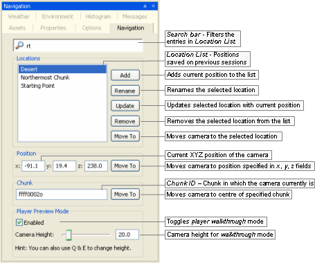
Navigation panel
The list below describes the fields on this panel:
Locations
Search bar
Restricts the locations displayed in the list to the ones containing the typed string. The list is refreshed automatically as the string is typed.
Location list
List of positions saved on previous sessions.
Add
Adds the current camera position to the list.
Rename
Renames the selected location.
Update
Updates the selected location with the current camera position.
Remove
Removes the selected location from the list.
Move to
Moves camera to the selected location.
Position
x,y,z
Current XYZ position of the camera, dynamically updated by World Editor.
Move to
Moves camera to the XYZ position specified by the user.
Chunk
Chunk ID
Chunk in which the camera currently is, dynamically updated by World Editor.
Move to
Moves camera to the centre of specified chunk.
Player preview mode
Enabled
Toggles the player walkthrough mode, in which the camera moves in the world as if attached to the player. This mode can be toggled via ~ (tilde) keyboard shortcut.
Camera height
Height of the camera during player walkthrough mode.
This panel allows you to create and edit weather systems, and specify which kind of weather should display in which space.
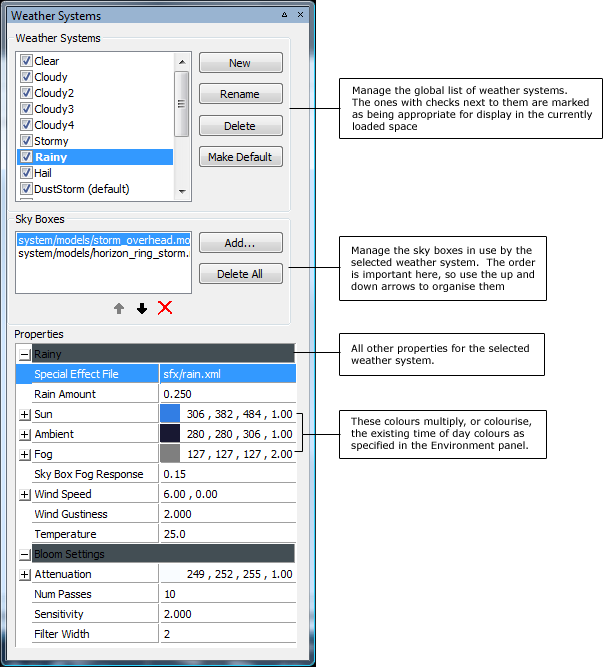
Weather Preview panel
The list below describes the fields on this panel:
Weather Systems list
List of all available weather systems for your game. Systems are included / excluded from the current space by using the checkboxes next to the system name.
New
Create a new weather system.
Rename
Rename the currently selected system. You can achieve this also by pressing F2 or double-clicking on the system name.
Delete
Delete the currently selected system.
Make Default
Set the current selected weather system as the default weather system for this space.
Sky Boxes list
List of the sky boxes used by the weather system. These can be any .model files, although the .model files should use one of the environment shaders in order to display correctly at the far plane.
Add...
Add a new sky box to the selected weather system. Pressing this button invokes a dialog box allowing you to select a .model file. An easier way to add sky boxes to your weather system is to simply drag and drop them from the Asset Browser.
Delete All
Delete all sky boxes from the list.
Properties
Property editor for all other weather system properties.
Special Effect File
This field accepts any Special Effect XML file. However, the effect file needs to be authored specifically for weather systems - adding an explosion effect here wouldn't make much sense. You can drag and drop files from the Special Effects virtual folder in the Asset Browser.
Rain Amount
How much of the built-in rain effect to play. The built-in rain effect layers 4 sheets of rain texture over the camera, and has a built-in fog emitter.
Sun
How to colourise the time-of-day sunlight (see the Environment page). Setting this value to white will mean the weather system has no effect on the normal sunlight colours. The multiplier field allows you to set a sunlight colour, and then adjust its brightness independently. Note that this allows you to overbrighten the sunlight colour, although on some low-end cards this will not work as desired.
Ambient
Similar to the sun colour above, but affects the Ambient light.
Fog
Colourises the time-of-day fog colour. The 4th field represents the fog density. This is interpreted as 'additional fogging.' The standard fogging value (1.0) reaches the far plane to hide clipping, and tries to not interfere with the rest of the scene too much. Dialing up the density of the fog brings the fog closer to the camera.
Sky Box Fog Response
Specifies how much the skyboxes should respond to any extra fog dialed in via the fog density slider. For any fog value greater than the default of 1.0, a certain amount of that is applied to the sky boxes - this is the sky box fog response value.
Wind Speed
Set the base wind speed for the weather. The wind affects the cloud layers, the flora, the trees, and the particle systems. This X/Z wind speed is in world coordinates, in metres per second.
Wind Gustiness
Set the gustiness of the wind, or, how much the wind varies around the base wind speed value.
Temperature
Sets the base temperature level for the weather system. Currently this value is not used by the default weather system engine.
Bloom Settings
This group sets up the blooming filter to further enhance the mood set by the selected weather system.
Attenuation
This is a colour multiplier that tints the colour of each stage of the bloom/blur filter, thus affecting the final colour of the bloom effect. Since it is applied per-pass to the filter, it is closely linked to the number of passes. With a higher number of passes, the blooming is very sensitive to the colour attenuation values, and so the colour attenuation will need to be fairly close to pure white.
Num Passes
Sets the number of blur passes performed by the bloom filter. While increasing this number does cost in terms of fill-rate, the cost is relatively small because the bloom filter uses quarter-size render targets to perform the blurring passes.
Sensitivity
This value specifies how sensitive the bloom filter is to bright colours on the screen. Setting this to a very low value makes causes the filter to respond to all intensities of colour in the frame buffer, creating more of a blur effect than a blooming one. Higher values cause the filter to react to just the brighter regions of the frame buffer, creating more of a traditional bloom effect. In the underlying bloom filter, the sensitivity is the mathematical exponent used to high-pass filter the back buffer to select the colours used in the blurring passes.
Filter Width
Sets the width, in texels, of the bloom filter kernel. The default value is 1, which provides the best quality effect, but will require a higher number of passes to achieve a large bloom spread. Higher values increase the width of the bloom spread, but if the filter width is too high, you will see fragmentation in the bloom filter as it skips pixels during the blur phase. This fragmentation caused by a higher filter width can be fixed by increasing the number of blurring passes, since it is cumulative effect.
This panel allows you to specify environment settings to change world's overall rendering.
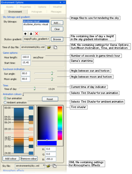
Environment Options panel (top)
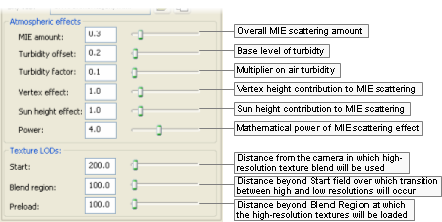
Environment Options panel (bottom)
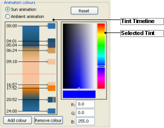
Tint Shader
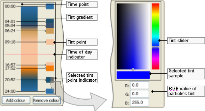
Tint Timeline and Selected Tint
The list below describes the fields on this panel:
Sky bitmaps and gradient
Sky bitmaps
List of image files to display as the sky. If more than one file is specified, then they are superimposed in the world. The Weather Systems entry in the list is always there, and cannot be deleted. It refers to the sky boxes in use by whatever Weather System is currently displayed. This item is included in the list so that you can sort the space's sky boxes with respect to the weather system ones.
Skybox gradient
File containing time of day x height in the sky gradient information.
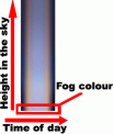
Skybox gradient mechanism
Time Of Day File fields
Time of day file
XML file containing the settings for the fields in the following group boxes:
Game Options
Sun/Moon Inclination
Time
Animation Colours

Opens the Open dialog box, where yon can specify the Time Of Day File.

Open the Saves As dialog box, where you can save the current settings to a new XML time-of-day file.
Game options
Hour length
Number of seconds in an hour of game world's time.
Start time
Time of day in which the game should start.
Sun/moon inclination
Sun angle
Angle formed between sun and the horizon. Value ranges from 0° to 90°.
Moon angle
Angle formed between sun and the horizon. Value ranges from 0° to 90°.
Time
Time of day
Current time of day in the world.
This value changes, and can also be changed by dragging Tint Timeline's Time Of Day bar, and by clicking Tint Timeline's Tint Gradient.
Animation colours
Sun animation
Selects Tint Shader for sun animation.
Ambient animation
Selects Tint Shader for sun animation.
Reset
Resets Tint Shader values for selected animation (sun or ambient).
These values are the same ones used for FantasyDemo.
Tint Timeline
Time point
Point of transition between two tints.
Can be dragged up and down (except the first and last one), with value being automatically updated.
Tint gradient
Displays the tint on each Tint Point, and the values in between.
Clicking the Tint Gradient changes Time Of Day to respective time.
Tint point
Tint selected for the time of day.
Can be dragged up and down (except the first and last one), with value in the timescale being automatically updated.
Time of day indicator
Sets the current time of day in the world.
This bar changes, and can also be changed by Time Of Day slider and by clicking the Tint Gradient.
Selected tint point indicator
Indicates which Tint Point is currently selected.
Selected Tint group is automatically updated to reflect the selected tint values.
Selected tint
Tint slider/ selector
Composed of 2 parts:
Slider — Colour to be applied to the particle in the selected Time Point.
Selector — Luminosity of the colour selected in the slider part of this field.
The tint might be also be specified in the RGB Value fields.
The Tint Gradient and Tint Point in the Tint Timeline, and the RGB Values are automatically updated with the values selected.
Selected tint sample
Displays the tint selected in Tint Slider/Selector.
RGB values
R, G, B
Red, green, and blue components of the tint in the selected Time Point.
The tint might also be specified in the Tint Slider/Selector.
The Tint Gradient and Tint Point in the Tint Timeline, and the Tint Slider/Selector are automatically updated with the values specified.
Add colour
Adds a new Time Point in the Tint Timeline.
The new Time Point is added on top of the final one, so it is not immediately visible to the user. You have to drag it up in the Tint Timeline before specifying its settings.
Remove colour
Deletes the Time Point currently selected in the Tint Timeline. The first and last Time Points cannot be deleted.
Sky file fields
Sky file
XML file containing the settings for fields in the Atmospheric Effects group box.

Opens the Open dialog box, where yon can specify the Sky File.

Open the Saves As dialog box, where you can save the current settings to a new XML time-of-day file.
Atmospheric effects
For details on these settings, see the Content Creation Manual's lesson Change Environmental Settings → Changing dynamic environment settings.
MIE amount
Overall MIE scattering amount.
This is the amount of scattering effect, which simulates forward scattering of light as it travels through the atmosphere.
Turbidity offset
Base level of turbidity, or amount of suspended particulate matter.
Proportionally affects MIE scattering effect.
Turbidity factor
Multiplier on air turbidity.
It defines how MIE scattering effect responds to increases in the global fog amount.
Vertex effect
Vertex height contribution to MIE scattering.
The vertex effect gives the scattering an elongated shape at the horizon.
Sun height effect
Sun height contribution to MIE scattering.
The sun height effect decreases the overall amount of the effect when the sun is high in the sky (i.e., noon).
Power
Mathematical power of MIE scattering effect.
It makes the effect look less like a flat shaded circle, and more like a circular gradient with emphasis being put on white nearer the sun.
Texture LODs
Start
Distance in metres from the camera in which high-resolution texture blend will be used.
Higher values will result in better visual results (especially on steep terrain), but will result in higher memory use.
Recommend value is between 200 and 1,000.
Blend region
Distance in metres beyond Start field over which transition between high and low resolutions will occur.
Recommended value is between 100 and 500.
Preload
Distance in metres beyond Blend Region at which the high-resolution textures will be loaded.
Recommend value is between 100 and 200.
This panel allows you to gauge the amount of luminance and colour in the scene, giving the world builder the ability to analyse the scene regarding the balance in the distribution of colours across the spectrum.
You can also use F11 (for details, see Keyboard shortcuts) to show the histograms in World Editor's main window — for details, see Histogram console.
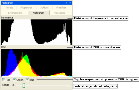
Histogram panel
The list below describes the fields on this panel:
Luminance
Distribution of luminance in the current scene.
RGB
Distribution of red, green, and blue colours in the current scene.
Red, Green, Blue
Toggles the graphing of the respective colour component in the histograms.
Range
Sets the vertical range ratio of the Luminance and RGB histograms.
A value of 1 causes the histograms to be graphed using the whole vertical size of the panel to plot the maximum values. The value of this field will be multiplied by the value in y-axis, thus augmenting the graphing size of components that would be otherwise too small to be graphed. The series of screenshots below display the RGB histogram being graphed with the following values for Range (respectively): 1, 2, 4, and 8.

Range = 1

Range = 2

Range = 4

Range = 8
This panel displays error, debug, and general information messages output by the tool.
To simplify debugging, these messages are also logged to bigworld/tools/worldeditor/worldeditor.log (for details, see Activity logging).
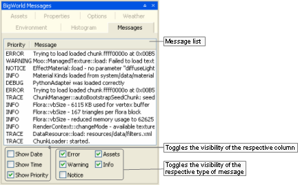
BigWorld Messages panel
The list below describes the fields on this panel:
Show data, Show time, Show priority
Toggles the visibility of the respective column.
Error, Warning, Notice, Assets, Info
Toggles the visibility of the respective type of message.
Please note that the Info check box toggles the visibility of Info, Trace and Debug messages.
Note
Asset errors are listed in bold letters as tree entries.
Those entries can be clicked to reveal the instances of the missing asset — each sub-item acts as a link that moves the view to the bounds of the missing asset.
The following sections highlight some important details about elements in World Editor.
There are two types of chunks in BigWorld:
Outdoor chunks
Have a fixed size of 100x100 metres.
Indoor chunks
Also called shells, have the size and shape determined by the models that represent them.
Each chunk can have any number of chunk items associated with it. For example, indoor chunks may have chunk items such as lights, tables, and chairs, while outdoor chunks may have trees, rocks, or the terrain (the terrain is not a chunk in itself, only a chunk item).
Restricted to indoor chunks, chunk templates are useful to reuse the lighting settings of a shell.
When a shell that for which a chunk template was saved in placed in the world, World Editor automatically places the lights specified by the template in that shell.
To save a chunk as a template, select the Edit → Save Chunk As Template menu item.
Current versions of World Editor do not offer a mechanism to resize an existing space. Instead, what has to be done is to create a new space with the desired dimensions, then move the existing objects to it. There are two ways to do this, one is to copy all the old space's files except space.settings file into the new space's directory. This will mean that old space information will override the new space information for each chunk. The limitation of enlarging the space through this way is you can only enlarge the space with the old space information in the center.
Another way is to resize the space using prefabs. The list below describes each step of this process:
Load the space for which you want to add/delete chunks (if different from current one)
Select the File → Open Space menu itemA — the Browse For Folder dialog boxB will be displayed. If there are unsaved changes, then the Changed Files dialog boxB will be displayed. Choose the appropriate answer for you case.
Select the space which size you want to change, then click the Open Space button — the selected space will be loaded.
Select desired world items
Set the Object panel'sC Selection Filter drop-down list box to All.
Select the Edit → Select All menu itemA, to select all objects in the space (if you want to enlarge space). Or, select desired chunks and all objects in them by drawing a rectangle around them using mouse dragging.
Save selected world items to a prefab file
Select the Edit → Save Selection As Prefab menu itemA — the Save As dialog boxB will be displayed.
Specify the name and folder in which you want to save the file, then click the Save button.
Select the File → New Space menu itemA — the New Space dialog boxB will be displayed.
Specify the name of the space and its dimensions, then click the Create button — the new space will be created and loaded.
Import world items from saved prefab file
In the Asset BrowserD, select the Prefabs virtual folder.
In the Asset List, select the file saved in step 3.
Move the mouse over the viewport, then press EnterE.
The objects saved on the old space have now been added to the new space. Note: The existing terrain inside the prefab's bound will be replaced by the terrain saved in the prefab. If you put the prefab in the wrong place and want to correct it, you have to undo the placing and place the prefab again.
A — For details, see Menu items.
B — For details, see Dialog boxes.
C — For details, see Object panel.
D — For details, see Asset Browser panel.
E — For details, see Keyboard shortcuts.
A portal links chunks, allowing traverse and visibility between them. When portals are connected, they become invisible — a complete world should not have visible portals.
For indoor chunks, portals form part of the shell, and can be modified in any 3D package — in World Editor they can be selected, but not changed. Indoor portals are only visible when disconnected from other indoor portals.
A portal in 3ds Max can be flagged as an exit portal, meaning that it will open up to the terrain, rather than to another indoor chunk. Exit portals are not visible in World Editor. When a shell with an exit portal is placed in the world, the chunk in which it is placed creates a new virtual boundary and a new portal to match the now adjacent indoor chunk. Other than this, outdoor chunks have fixed portals to adjacent outdoor chunks which should not be changed — which is why they cannot be selected in World Editor.
Note that the external flag in the properties of a portal is deprecated, although it still causes the portal to be shaded to yellow. But other than that, the flag has no technical effect.
Directional lights spread an even light over an area, unlike other kinds of light, which spread out from a specific point.
They are useful for things like the sun, whose source is very distant, and whose light needs to affect a large area. As a result, directional lights are not available for indoor chunks, which should use omni and ambient lighting instead.
For more details on the different kind of lights, see Lighting Setup panel.
When a model is placed in World Editor, the centre of its bounding box is used to determine the chunk in which the model will be placed.
This is suitable for most situations — placing an object in a room causes the object to be associated to that room, placing an object outdoors causes the object to be associated with an outdoor chunk.
But it might not be suitable in cases where there is a single indoor shell with an exit portal, and you want to place an enclosing outer wall around that shell. In this case, the wall and the interior shell will be approximately the same size, and will be placed in approximately the same location. In this scenario, World Editor would automatically place the outer walls inside the shell. This would mean that the external walls only get lit by the indoor lights, and would be bound by the visibility rules of that indoor shell's exit portal.
To overcome this problem, models have the outside only flag (accessed via the Properties panel (for details, see Properties panel).
After changing this value to true, World Editor will automatically change the model's location to an outdoor chunk. Additionally, as you move that model around the world, World Editor makes sure that it is never placed in an indoor chunk.
If you have a model that will need to be always designated as outside only, then you can do it by editing the .model file, as in the example below:
<rock.model> ... <editorOnly>
Example file rock.model
| Make sure to follow the exact capitalization for the inserted text. |
If World Editor starts rendering your space with random colours or adding objects by its own accord, then you can force it to regenerate the space map by deleting the cache.
In order to regenerate the space, follow the steps below:
Shut down World Editor.
Browse to the folder containing the space you were working in —
<res>/spaces/<space>.In that folder, delete the files space.thumbnail.dds and space.thumbnail.timestamps.
Restart World Editor.
The space map will be recreated.
If this problem keeps occurring, then please contact the BigWorld support engineers, providing the following information:
Your machine's graphics card
Version of your video drivers.
To create a new world, the first step is to create a space using the File → New Space menu item.
After that, create a hand-drawn map of the whole world — as simple or as detailed as desired —, making sure that it is to scale. This hand-drawn map will act as a guide for the artists creating the world — they will be able to follow the guidelines in the map for performing task such as choosing the regions to lock for editing.
The bitmap can have any size, as long as it is proportional to your space. For example, if your space is 200x150 chunks, then your bitmap could be 640x480.
Once having drawn the world, save it as space.map.bmp in your newly created space folder and commit it alongside the map texture to the CVS repository.
All files relating to the new space (located in
<res>/spaces/<space>)
will have to be checked out on the machines that will be editing it with
World Editor.
The Lock Server (bwlockd) can work with any new spaces committed to your server without having to be restarted.
For more details on the Lock Server, see Lock Server (BWLockD).
Errors regarding bwlockd are displayed in the message window. The list below describes the meaning of some of the errors you might come across, and how to correct them:
Unable to connect to bwlockd
Generic error message displayed after any problem with the Lock Server.
Look at the error message above this one to determine the specific problem.
Connect(): Couldn't connect, last error is 10061
The Lock Server is not running, or you have specified an incorrect host or port number in World Editor's configuration file bigworld/tools/worldeditor/options.xml, tag <bwlockd> (for details on this file's grammar, see the document File Grammar Guide's section options.xml → World Editor.)
Make sure that the server is running, the specified host is correct, and the specified port is 8168.
Connect(): Couldn't set lockspace
The space you are currently editing could not be found by the Lock Server.
Make sure that you have chosen the correct space, and that it is checked out on the server, so the Lock Server can find it.
In order to provide a trace of the activities performed by the user, thus simplifying the debug process, all on-screen warning and errors (displayed in the BigWorld Messages panel (for details, see BigWorld Messages panel) are logged to file bigworld/tools/worldeditor/worldeditor.log.
Apart from errors and warning, actions like changing the Object panel's Selection Filter or Locking Mode, or saving the scene, are also logged to file.
The example below illustrates an example of the generated log file.
/------------------------------------------------------------------------\ WorldEditor 1.8 (compiled at Oct 11 2006 at 20:20:16) starting on 11/15/06 Action: entered Object modeAction: Entering XZ snap mode Action: characters/npc/chicken/chicken.model
Action: Selection Filter: All Action: Added model Critical: Saving... Action: Calculating lighting for 00000026i
Action: Calculating thumbnails for 00000002o Action: Calculating thumbnails for 00000026i Action: Saving 00000002o Action: Saving 00000026i Critical: Save complete
Example BigWorld log file
| During startup: Settings applied |
| During startup: Critical errors |
| During session: Settings were changed |
| During session: A model was added |
| During session: The modified scene was saved |
A specific type of User Data Object (UDO) has been implemented, called PatrolNode, that allows the creation and editing of patrol paths (or any other situation that requires a fixed directional graph).
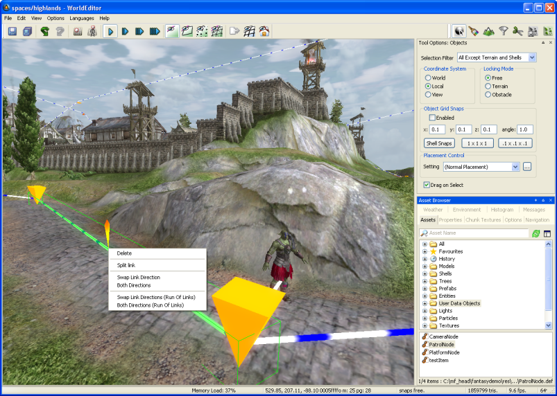
Example patrol path using the PatrolNode user data object
Patrol path graphs consist of a collection of nodes and directional links between them. In addition, entities can support linking to patrol paths.
To create a patrol path graph, click the Asset Browser panel (for details, see Asset Browser panel), then select the User Data Objects virtual folder, and drag the PatrolNode object onto the viewport — this will create the first node in the graph.
Nodes have a special patrol node gizmo, with four selectable areas — two circles and two crosses. The crosses can be used to create more nodes, by clicking and dragging them to the location desired for the new node. A link is automatically created, from the original node to the new one.
To create a link from one node to another, select the first node, then drag the circle area onto the other node. As you drag, the colour of the link changes from red (which means that a link cannot be established at this location) to green (which means that a link can be established at this location) when the cursor is moved over the second node.
By default, links are shown to follow the ground. If either node is in the air however, the link will go in a straight line.
Standard editing operations can be done on nodes — they can be deleted, cloned, and moved.
When the mouse cursor is placed over a link, it will be highlighted with a green box. A context menu will then be available (by right-clicking the link), with the following items:
Delete
Deletes the link.
Swap link direction
Changes the direction of the link.
Both directions
Changes the link type to bi-directional.
Swap link directions (run of links)
Swaps the directions of a run of linksA.
Both directions (run of links)
Changes a run of linksA type to bi-directional.
Split Link
Splits the link at the middle.
A — A run of links includes the current link and goes in each direction until a complete loop is done, a node with only one link going into it is found, or a node with more than one link is found.
To support patrol paths, or to be able to link to any other user data object for that matter, an entity needs to have a UDO_REF type property which allows linking (for details, see the document Server Programming Guide's section Directory Structure for Entity Scripting → The Entity Definition File)
These entities can be linked to a PatrolNode user data object. Such an entity will have a linking gizmo, but only with the two circles (it can only be linked, it cannot create nodes). To associate an entity with a PatrolNode user data object, drag one of the circles to a node in the patrol graph — a link will be drawn from the entity to the node.
For an example of a definition file suitable for patrol paths, see fantasydemo/res/scripts/entity_defs/Guard.def.
The file fantasydemo/res/scripts/cell/Guard.py is a Python script that runs on the server to control guards. It uses PatrolNode based patrol paths to optionally set guards on a patrol path, using the doPatrol method. Note that it also uses the patrolRadius property (set in the definition file) to allow a degree of randomization on the adherence to the path.
Here we describe some useful Python scripts that are built into World Editor. The scripts should be used with caution - they will operate directly on the space and cannot be undone. To access these scripts bring up the Python console (Ctrl+P) and type one of the following:
WorldEditor.restitchAllTerrainBlocks()
This will restitch the edges of terrain blocks in the current space so that they match. Occasionally cracks appear between chunks. Usually this can be fixed by painting with a zero-strength height brush over the cracks. This script will fix this issue for the entire space.
WorldEditor.regenerateThumbnails()
This will regenerate all of the thumbnails in the current space that are used in the project view.
WorldEditor.convertSpaceToZip()
This will convert the current space to use ZipSections instead of BinSections.
WorldEditor.regenerateLODs()
This will force the regeneration of terrain texture LODs on the current space.
Table of Contents
Model Editor is designed to be used in conjunction with other tools from the BigWorld Toolkit.
It is used to create new materials and view exported models and animations under various lighting conditions.
With Model Editor you can simulate various game environments, allowing you to preview what the model will look like in the game engine, and to create effects such as shaders that are not supported by 3ds Max.
Problems in the mesh and animations of your model may also be identified. You can view the level of detail as created by the game engine to ensure that it appears as expected.
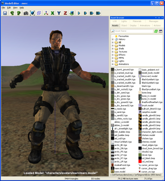
Model Editor window
For details on how to start this and other BigWorld tools, see Starting the Tools.
The list below describes the menu items available in Model Editor:
File → Open model
Opens the Open dialog box, where you can specify a .model file to load.
File → Add model
Adds the selected model to the viewport, so it can be viewed alongside the current model — this is useful when editing a model that is part of a SuperModel.
Please note that added models cannot be changed, only viewed.
File → Remove added models
Removes from the viewport all models that have been added to be viewed alongside the current model.
File → Revert to saved
Discards all changes made to the model, and loads its saved version.
File → Save
Saves the current model and any other modified files.
File → Reload all textures
Reloads from disk all texture files applied to the model — this is useful to refresh modified textures.
File → Regenerate visibility box
Regenerates the model's visibility box using its animations — this is the box used in the client for visibility and shadowing.
File → Recent models
Opens a sub-menu with the list of recently opened models.
File → Recent lights
Opens a sub-menu with the list of recently opened lights.
File → Exit
Closes the application.
The user will be prompted to save changes to the model or lighting settings.
Edit → Undo
Undoes the most recent model-changing action.
Multiple actions can be undone. The undo list extends to the state of the model when it was loaded.
Each model-changing action that is undone is added to the redo list.
Also accessible via the Undo toolbar buttonA (
 ).
).Note
Only actions that effectively change the model are added to the undo list.
Actions added to the undo list:
Changing the model's material.
Adding/removing animations.
Adding/removing LODs.
Not added to the undo list:
Changing the Materials Settings panel's Preview check box.
Changing any field in the Display Settings panel.
Changing camera height and/or angle.
Edit → Redo
Redoes the most recently undone model-changing action.
Multiple actions can be redone.
The redo list contains one entry for each undone model-changing action.
Also accessible via the Redo toolbar buttonA (
 ).
).Edit → Preferences
Opens the Model Editor Preferences dialog box (for details, see Preferences dialog box), which allows you to customise editor and environment options.
View → Toolbar → Main toolbar
Toggles the visibility of Model Editor's toolbar.
View → Show Asset Browser panel
Displays/activates the panel (for details, see Asset Browser panel).A
View → Show Display panel
Displays/activates the panel (for details, see Display Settings panel).A
View → Show Object panel
Displays/activates the panel (for details, see Object Properties panel).A
View → Show Animations panel
Displays/activates the panel (for details, see Animations panel).A
View → Show Actions panel
Displays/activates the panel (for details, see Actions panel).A
View → Show LOD Panel
Displays/activates the panel (for details, see Level Of Detail panel).A
View → Show Lights Panel
Displays/activates the panel (for details, see Lighting Setup panel).A
View → Show Materials Panel
Displays/activates the panel (for details, see Materials Settings panel).A
View → Show Messages Panel
Displays/activates the panel (for details, see BigWorld Messages panel).A
View → Show Panels
Toggles the visibility of all panels.A
View → Load Default Panel Layout
Closes all customised panels and displays Model Editor's default panel layout.A
View → Load Most Recent Panel Layout
Closes all current panels and displays the customised panel layout previously used.A
Languages → List of available languages
Selects the language to use in the tool.
This list is compiled based on the LanguageName tags present in the XML files in the
<res>/helpers/languages folder and in the file pointed by the language tag in bigworld/tools/modeleditor/options.xml.Help → About Model Editor
Opens the Model Editor version dialog box.
Help → Tools Reference Guide
Opens this document.
Help → Content creation
Opens the document Content Creation Manual.
Help → Shortcuts
Opens the Model Editor Keyboard Shortcuts dialog box.
For details, see Model Editor Shortcuts dialog box.
Help → Request feature/report bug
Opens your e-mail program, with the To: field automatically set to BigWorld's support e-mail address, and the Subject: field set to Model Editor — Feature Request / Bug Report.
A — For details on the panel system and its terminology, see Panel System.
The list below describes the toolbar buttons available in Model Editor:
 — Save
 Saves the current model.
Performs the same function as the File → Save menu item.A
- — Undo
Undoes the most recent action.
Performs the same function as the Edit → Undo menu item.A
- — Redo
Redoes the most recent undone action.
Performs the same function as Edit → Redo menu item.A
 — Create
thumbnail
— Create
thumbnailCaptures a thumbnail of the current view of the loaded model.
This thumbnail is used in the Object Properties panel, and by the Asset BrowserA in other tools of the BigWorld Toolkit.
 — Zoom to
extents
— Zoom to
extentsMoves the camera so that the model is brought to the centre of the screen.
This is useful if you have moved the camera far from the model, and needs to quickly centre it again.
 — Display bounding
box
— Display bounding
boxToggles the visibility of the model's bounding box (yellow) and visibility box (blue).
Same as the Display Settings panel's Show Bounding Box check box.
 — Free
positioning
— Free
positioningSets camera movement to a swivel action — the camera can be swivelled by dragging the right mouse button.
Keyboard movement keys will move the camera.
 —
X-locked
—
X-lockedLocks camera movement to the x-axis.B
 —
Y-locked
—
Y-lockedLocks camera movement to the y-axis.B
 —
Z-locked
—
Z-lockedLocks camera movement to the z-axis.B
 — Orbit
camera
— Orbit
cameraToggles camera pivot movement around the geometric centre of model.
You can change the orbit direction by pressing d (clockwise camera rotation) or a (counter-clockwise camera rotation).
 — Slow,
 —
Medium,
—
Medium,  — Fast,
 — Super
fast
— Super
fastSpecifies how fast the camera travels in response to appropriate key events.
If Caps Lock is onA, then the camera speed will be boosted.
A — For details, see Menu items.
B — Swivelling the camera (by dragging the right mouse button) sets the camera mode to Free Positioning.
The status bar displays information about the current scene. A typical status bar is illustrated below:

Model Editor toolbar
The list below lists the pieces of information displayed in the status bar, as they appear:
Menu item pointed at (in the example, Get Information about Model Editor)
Help text for the menu item currently pointed at.
Triangles rendered (in the example, 7236 triangles)
Number of triangles currently being rendered in the scene.
Model nodes (in the example, 172 nodes)
Number of nodes on the model currently rendered.
Model BlendBone nodes (in the example, 85 BlendBone nodes)
Number of BlendBone nodes for the current model.
Texture size in memory (in the example, 2.61 Bytes texture memory)
Amount of texture memory being used by the loaded model.
Frame rate (in the example, FPS: 234)
Current frame rate being used to display the scene.
The list of Model Editor's keyboard shortcuts can be displayed via the Help → Shortcuts menu item (for details, see Menu items).
The sections below list the Model Editor's keyboard shortcuts:
F1
Displays the Model Editor Shortcuts page, which can be left by pressing Esc.
Ctrl+F5
Activates the Realtime Profiling console, which can be left by pressing Esc — for details, see Realtime Profiling console.
Ctrl+F7
Activates the Debug (Watcher) console, which can be left by pressing Esc — for details, see Debug (Watcher) console.
Alt
If Debug (Watcher) consoleA is active
If [0-9] key in the alphanumeric keypad is pressed:
Selects item 40+[0-9], or 50+[0-9] (if Shift is pressed).
If used to drag-and-drop from Asset BrowserB to viewport
Adds the dragged model (with read-only permission) to the viewport, so it can be viewed alongside the current model. This is useful for editing models that are part of a SuperModelC.
Performs the same function as the File → Add Model menu item. For details, see Menu items.
Ctrl
If Debug (Watcher) consoleA is active
If [0-9] key in the alphanumeric keypad is pressed:
Selects item 20+[0-9], or 30+[0-9] (if Shift is pressed).
If used to drag-and-drop from Asset BrowserB to viewport
Adds the dragged model (with read-only permission) to the viewport, so it can be viewed alongside the current model. This is useful for editing models that are part of a SuperModelC.
Performs the same function as the File → Add Model menu item. For details, see Menu items.
Shift
If Debug (Watcher) consoleA is active
If [0-9] key in the alphanumeric keypad is pressed:
Selects item 10+[0-9], 30+[0-9] (if Ctrl is pressed), or 50+[0-9] (if Alt is pressed).
Shift+Enter
If Debug (Watcher) consoleA is active
If watcher is in Edit mode
Displays the watcher modification history.
A — Activated by F7 (for details, see Debug (Watcher) console).
B — For details, see Asset Browser panel.
C — For details, see the document Client Programming Guide's section Models → SuperModel.
Backspace
If Debug (Watcher) consoleA is active
Returns the list to the previous branch of the watcher tree.
Caps Lock
ON
Increases the current camera speed. It will accelerate the camera movement, which speed is set by keyboard shortcuts (Ctrl+1, Ctrl+2, Ctrl+3, and Ctrl+4), or by the Camera Speed toolbar buttons (
,,, and )B.OFF
Restores the camera speed set by keyboard shortcuts or by the Camera Speed toolbar buttonsB.
Enter
If Python consoleC is active and no command is specified
Executes the Python command, or exits the console if no command was specified.
If Realtime Profiling consoleD is active
Expands or collapses the profiling element currently selected — elements with children are indicated by an ellipsis (…) next to it.
If Debug (Watcher) consoleA is active
If the selected node is not a leaf
Navigates one level down in the watcher tree.
If the selected node is a leaf
Opens the selected watcher for editing, or accepts the typed value if it is already in Edit mode.
If watcher is in Edit mode and Shift is pressed
Displays the watcher modification history.
Esc
Deselects the selected objects.
If any console is active
Exits the console.
NOTE: The different modes and consoles are activated in the following way:
Help mode — F1
Realtime profiling console — F5 (for details, see Realtime Profiling console)
Debug (Watcher) console — F7 (for details, see Debug (Watcher) console)
Python console — Ctrl+P (for details, see Python console)
If Debug (Watcher) consoleA is active
If the watcher is in Edit mode:
Leaves Edit mode.
If the watcher is not in Edit mode:
Exits the console.
Home
If Realtime Profiling consoleD is active
Scrolls the list to display the first page.
If Debug (Watcher) consoleA is active
Returns the list to the root of the watcher tree.
Page Down
If Realtime Profiling consoleD is active
Moves the selection to the next element in the list.
Performs the same function as the ] (square right bracket) keyboard shortcut.
If Debug (Watcher) consoleA is active
If the watcher is not in Edit mode
Moves the selection to the next item in the list.
If the watcher is in Edit mode
Decreases the watcher's value by 1, 10 (if Shift is pressed), 100 (if Ctrl is pressed), or 1,000 (if Alt is pressed).
Page Up
If Realtime Profiling consoleD is active
Moves the selection to the previous profiling element in the list.
Performs the same function as the [ (square left bracket) keyboard shortcut.
If Debug (Watcher) consoleA is active
If the watcher is not in Edit mode
Moves the selection to the previous item in the list.
If the watcher is in Edit mode
Increases the watcher's value by 1, 10 (if Shift is pressed), 100 (if Ctrl is pressed), or 1,000 (if Alt is pressed).
A — Activated by F7 (for details, see Debug (Watcher) console).
B — For details, see Toolbar.
C — Activated by Ctrl+P (for details, see Python console).
D — Activated by F5 (for details, see Realtime Profiling console).
Numpad + (Plus sign)
If Realtime Profiling consoleB is active
Scrolls the screen one line down.
If Debug (Watcher) consoleA is active
Scrolls the watcher list down.
Numpad - (Minus sign)
If Realtime Profiling consoleB is active
Scrolls the screen one line up.
If Debug (Watcher) consoleA is active
Scrolls the watcher list up.
[ (Left square bracket)
If Realtime Profiling consoleB is active
Moves the selection to the profiling element in the list.
Performs the same function as the Page Up keyboard shortcut.C
] (Right square bracket)
If Realtime Profiling consoleB is active
Moves selection to the next profiling element in the list.
Performs the same function as the Page Down keyboard shortcutC.
A — Activated by F7 (for details, see Debug (Watcher) console).
B — Activated by F5 (for details, see Realtime Profiling console).
C — For details, see Edit keys.
Alphanumeric keypad
If Debug (Watcher) consoleA is active
Depending on the key modifier pressed (if any), selects the following item (n is the pressed key):
n10+
n(if Shift is pressed)20+
n(if Ctrl is pressed)30+
n(if Ctrl+Shift is pressed)40+
n(if Alt is pressed)50+
n(if Alt+Shift is pressed)
A — Activated by F7 (for details, see Debug (Watcher) console).
A
Moves the camera to the left.
If the Orbit Camera toolbar button (
)A is
selectedIf the camera is rotating clockwise
Stops the camera rotation.
If the camera is not rotating
Rotates the camera counter-clockwise.
D
Moves the camera to the right.
If the Orbit Camera toolbar button (
)A is
selectedIf the camera is rotating counter-clockwise
Stops the camera rotation.
If the camera is not rotating
Rotates the camera clockwise.
E
Moves the camera upwards.
G
If Realtime Profiling consoleB is active
Draws a graph for the profiling element currently selected.
More than one element can be graphed at any one time. Each one will be assigned a different colour, which will be used to display the element's name, and draw the graph itself.
M
If Ctrl is pressed
Cycles through the available camera modes.
This value can also be set by the Camera Mode group of toolbar buttons (
 ,
, ,
, ,
, ).
).
Q
Moves the camera downwards.
W
Moves the camera forward.
S
Moves the camera backwards.
A — For details, see Toolbar.
B — Activated by F5 (for details, see Debug (Watcher) console).
Alt+F4
Accesses the File → Exit menu item.C
Alt+Page Down
If Debug (Watcher) consoleA is active and watcher is in Edit mode
Decreases the watcher's value by 1,000.
Alt+Page Up
If Debug (Watcher) consoleA is active and watcher is in Edit mode
Increases the watcher's value by 1,000.
Alt+[0-9]
If Debug (Watcher) consoleA is active and alphanumeric keypad was used
Selects list item 4[0-9].
Alt+Shift+[0-9]
If Debug (Watcher) consoleA is active and alphanumeric keypad was used
Selects list item 5[0-9].
Ctrl+Page Down
If Debug (Watcher) consoleA is active and watcher is in Edit mode
Decreases the watcher's value by 100.
Ctrl+Page Up
If Debug (Watcher) consoleA is active and watcher is in Edit mode
Increases the watcher's value by 100.
Ctrl+[0-9]
Ctrl+1 turns the Slow Camera toolbar buttonB (
) on.Ctrl+2 turns the Medium Speed Camera toolbar buttonB (
) on.Ctrl+3 turns the Fast Camera toolbar buttonB (
) on.Ctrl+4 turns the Super Fast Camera toolbar buttonB (
) on.If Debug (Watcher) consoleA is active and alphanumeric keypad was used
Selects item 2[0-9].
Ctrl+Shift+[0-9]
If Debug (Watcher) consoleA is active and alphanumeric keypad was used
Selects item 3[0-9].
Ctrl+A
Accesses the File → Add Model menu item.C
Ctrl+B
Accesses the File → Regenerate Bounding Box menu item.C
Ctrl+H
Accesses the View → Show Panels menu item.C
Ctrl+I
Cycles through the available camera speeds.
This value can also be set by the Camera Speed group of toolbar buttons —
,,,.Ctrl+M
Cycles through the available camera modes.
This value can also be set by the Camera Mode group of toolbar buttons —
,,,, .Ctrl+O
Accesses the File → Open Model menu item.C
Ctrl+P
Activates the Python console, which can be left by pressing Esc. For details, see Python console.
Ctrl+R
Accesses the File → Revert To Saved menu item.C
Ctrl+S
Accesses the File → Save menu item.C
Ctrl+T
Accesses the Edit → Reload All Textures menu item.C
Ctrl+Y
Accesses the Edit → Redo menu item.C
Ctrl+Z
Accesses Edit → Undo menu item.C
Note: The mouse cursor must be over the viewport for this shortcut to be enabled.
Shift+Alt+[0-9]
See entry Alt+Shift+[0-9] in this list.
Shift+Ctrl+[0-9]
See entry Ctrl+Shift+[0-9] in this list.
Shift+Enter
If Debug (Watcher) consoleA is active and watcher is in Edit mode
Displays the watcher modification history.
Shift+Page Down
If Debug (Watcher) consoleA is active and watcher is in Edit mode
Decreases the watcher's value by 1.
Shift+Page Up
If Debug (Watcher) consoleA is active and watcher is in Edit mode
Increases the watcher's value by 1.
A — Activated by F7 (for details, see Debug (Watcher) console).
B — For details, see Toolbar.
C — For details, see Menu items.
The list below lists the Model Editor's mouse controls:
Left button drag
If the mouse is dragged from an asset in the Asset Browser panel (for details, see Asset Browser panel)
For details, see Drag-and-drop
Right button drag
Moves the camera in the scene.
Dragging the mouse to the left and to the right always moves the camera in that direction. But the effect on up and down drag is determined by the Model Editor Preferences dialog box's Invert Mouse check boxA (the dialog box is accessed via the Edit → Preferences menu itemB).
The table below describes the camera's movement:
Drag direction Invert mouse Camera movement Model movement Left N/A Left Right Right N/A Right Left Forward 
Up Down 
Down Up Backwards Down Up Up Down If Alt or Ctrl is used to drag from the Asset Browser panel to the viewport (for details on Asset Browser, see Asset Browser panel)
Adds the dragged model (with read-only permission) to the viewport, so it can be viewed alongside the current model. This is useful for editing models that are part of a SuperModel (for details, see the document Client Programming Guide's section Models → SuperModel).
Performs the same function as the File → Add Model menu item. For details, see Menu items.
Middle button click
Moves the camera so that the model is brought to the centre of the screen.
Performs the same function as the Zoom To Extents toolbar button (
)C.Scroll wheel rotate
Moves the camera forward and backwards.
If Space key is pressed
Increases or decreases the camera speed, depending on the direction of the wheel rotation.
Performs the same functions as the
,,, and toolbar
buttons.C
A — For details, see Preferences dialog box.
B — For details, see Menu items.
C — For details, see Toolbar.
Accessed via the Edit → Preferences menu item, the Preferences dialog box allows you to customise editor, environment, and LOD (level of detail) options.
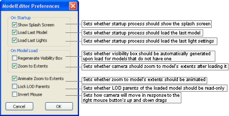
Model Editor Preferences dialog box
The list below describes the fields on this dialog box:
On startup
Show splash screen
Toggles the display of the application's splash screen.
Load last model
Toggles the automatic load on startup of the model file used on last session.
Load last lights
Toggles the automatic load on startup of the light file used on last session.
On model load
Regenerate visibility box
Determines whether a visibility box should be automatically generated upon load for models that do not have one.
Zoom to extents
Automatically zooms to show the entire model when loading.
Animate zoom to extents
Sets whether the zoom to model's extents should be animated.
Lock LOD parents
Sets whether LOD parents of the loaded model should be read-only.
Invert mouse
Toggles the camera orientation for the up and down mouse movements when using the mouse's right button.
Note that this setting does not affect the camera orientation for the left and right mouse movements.
Value Mouse movement Camera movement Model movement 
Up Up Down Down Down Up 
Up Down Up Down Up Down
Accessed by right-clicking any texture map in the Materials Settings panel's Properties Table (for details, see Material Properties table) and choosing either the Enable Texture Feed or the Change Texture Feed Name item in the context menu (for details, see Texture map context menu), this dialog box allows you to specify or change the name for the texture feed to be assigned to the invoking texture map.
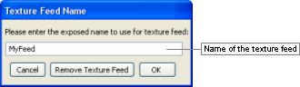
Texture Feed Name dialog box
The list below describes the fields on this dialog box:
Name
Name to assign to the texture feed.
Cancel
Closes the dialog box without assigning or changing name of texture feed.
Remove texture feed
Removes the texture feed currently assigned to the texture map.
This button will only be enabled if the invoking texture map already has a texture feed assigned to it.
OK
Assigns/changes name of the texture feed.
The name of the texture feed is displayed between parentheses next to the texture description.
Accessed via the Help → Shortcuts menu item, the Model Editor Shortcuts dialog box displays a list of shortcuts available on Model Editor. For details on the complete list, see Keyboard shortcuts.
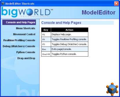
Model Editor Shortcuts dialog box
Assets used to populate the world can be accessed via the Asset Browser panel. For details, see Asset Browser panel.
This node lists all exported .model files. Models are the basic props that can be placed in world.
Note
For more information on models, see:
document Client Programming Guide's chapter Models.
document Content Creation Manual's lessons (document accessed by pressing F1 or by selecting the Help → Content Creation menu item — for details, see Menu items):
Modify a Model in Model Editor
Add Models to the World
Best Practices → Animation tree — Using LOD models to share animations
For details on .model files' grammar, see the document File Grammar Guide's section .model.
Shells refer to the indoor chunks containing portals, exported to the folder shells.
Note
For more information on shells, see:
document Content Creation Manual's lessons (document accessed by pressing F1 or by selecting the Help → Content Creation menu item — for details, see Menu items):
Create an Internal Shel
Create an Internal Area in World Editor Using Shells
Add Lights to the World → Lighting Environments
Outdoor-to-Indoor Transitions → Placing an interior shell
Textures refer to two-dimensional images of a surface used to cover 3D objects, which are assigned in the Materials Settings panel (for details on this panel, see Materials Settings panel) to material's various maps (e.g., normal, height, diffuse, specular, sub-surface).
Note
For more information on texture, see the document Content Creation Manual's lessons (document accessed by pressing F1 or by selecting the Help → Content Creation menu item — for details, see Menu items):
Create and Export a Static Object in 3ds Max and Maya → Referencing the object texture maps
Create Low-Polygon Characters → Referencing the character texture maps
Create and Apply Animated Texture Maps
Build and Use Normal Maps → Create Decal Textures
This node lists the effect files (.fx), which specify the effect to be applied to the selected material/tint (effect files are assigned in the Materials Settings panel (for details on this panel, see Materials Settings panel).
Note
For more information on effects, see:
document Client Programming Guide's section 3D Engine (Moo) → EffectMaterial
document Content Creation Manual's lessons (document accessed by pressing F1 or by selecting the Help → Content Creation menu item — for details, see Menu items):
Manage Resources → Non-specific resources
BigWorld shaders and Materials
Create a New Material
For details on the .fx file's grammar, see the document Client Programming Guide's section 3D Engine (Moo) → EffectMaterial → Format.
This node lists the material files (.mfm), which contain material information that includes bitmap references and effect files (.fx), which in turn gives Model Editor access to artist-editable features in that file (MFM files are assigned in the Materials Settings panel (for details on this panel, see Materials Settings panel).
Material files are a handy way of storing complex material property settings.
When a .mfm file is referenced in Model Editor, the content of that material file is copied to the model's visual file (.visual) — it does not dynamically reference the .mfm file. For details on visual files' grammar, see the document File Grammar Guide's section .visual.
Note
For more information on MFM, see the document Content Creation Manual's lessons (document accessed by pressing F1 or by selecting the Help → Content Creation menu item — for details, see Menu items):
Manage Resources → Organising art resources — Sets
BigWorld shaders and Materials
Create a New Material
Create and Apply Animated Texture Maps
For details on .mfm files' grammar, see the document File Grammar Guide's section .mfm.
This node lists pre-defined Model Editor Light (.mvl) files, which specify lighting settings that can be applied to the model, thus previewing how it will look when placed in the world.
Lighting settings can be applied to the model using the Lighting Setup panel (for details on this panel, see Lighting Setup panel).
Note
For details on .mvl files' grammar, see the document File Grammar Guide's section .mvl.
This node lists the animation files (.animation) created and exported by your 3D application.
Note
For more information on animations, see:
document Client Programming Guide's chapter Animation System.
document Content Creation Manual's lessons (document accessed by pressing F1 or by selecting the Help → Content Creation menu item — for details, see Menu items):
Create Character Movement Animations
Add Animations to Characters
Modify Animations with Actions
Create Animated or Interactive Entities
Best Practices → Animation tree — Using LOD models to share animations
Most of the GUI for interacting with models is contained in panels selectable via tabs.
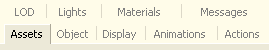
Model Editor panel
The following sub-sections describe each panel and the settings available on them.
This panel gives access to assets through the Asset Browser, an interface that is available in World Editor, Model Editor, and Particle Editor. For details, see Asset Browser.
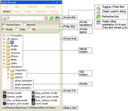
Asset Browser panel
Drag-and-drop operation is specific to the tool that implements it, and the type of asset being dragged , as described in the table below (asset types are listed in the order in which they appear in the Asset Tree):
| Asset type | Drop locationA | Effect |
|---|---|---|
A — If asset file is dropped in Favourites special virtual folder, then it is added to that folder. For details, see Asset file. | ||
| Animation | Animations panel's Animation list (for details on this field, see Animations panel) | Adds the dragged animation to the list of animations played for the current model. |
| Effect | Materials Settings panel's Properties table or Effect field (for details on this field, see Materials Settings panel) | Assigns the dragged effect/MFM file to the current material. |
| Light | Viewport | Applies the lighting setup described in the dragged file to the current model. This automatically selects the Custom Lighting option button in the Lighting Setup panel, and sets the Lighting Model drop-down list box with the selected file (for details, see Lighting Setup panel). |
| MFM | Same as Effect. | |
| Model | Viewport | Opens the dragged model/shell for editing.
|
| Object Properties panel's Editor Proxy Model field (for details on this field, see Object Properties panel) | Adds the dragged model as a new LOD level for the current model. | |
| Level Of Detail panel's LOD table (for details on this field, see Level Of Detail panel) | Sets the dragged model as the editor proxy model. | |
| Shell | Viewport | Opens the dragged shell for editing. |
| Texture | Display Settings panel's Choose Floor Texture button (for details on this field, see Display Settings panel) | Applies the dragged texture to the floor texture. |
| Materials Settings panel's Properties table's any map field — e.g., normal, height, diffuse, specular, sub-surface (for details on these fields, see Materials Settings panel) | Assigns the dragged texture to the map field. | |
Drag-and-drop operation in Model Editor's Asset Browser panel
Defined in Asset Browser's configuration file (for details, see Customisation), virtual folder list files of a specific asset type.
For details on the listed asset types, see Assets.
This panel allows you to specify the properties of the material of each component of the model. For details on material properties, see Materials Settings panel.
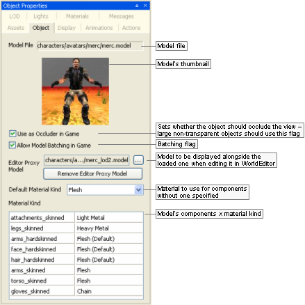
Object Properties panel
The list below describes the fields on this panel:
Model file
Model's file name, with full path.
Use as occluder in game
Indicates that the object should occlude the view (large non-transparent objects should use this flag). This information is used by UMBRA in the client to determine the visibility of objects behind the model.
Allow model batching in game
Indicates that the model allows batching. This can improve performance due to rendering optimisation, if there are several instances of a model appearing in the game. It is important to note that batched models cannot use tints.
Editor proxy model
Model to be displayed alongside the loaded one when editing it in World Editor.A Very small models are difficult to select, manipulate, and visualise in World Editor — by defining a proxy model, the builder has a better way to work with them. Please note that Model Editor also renders the proxy model alongside the current model.
Remove editor proxy model
Removes the proxy model specified for the current model.
Default material kind
Default material kind for the model (such as wood, glass, etc...), used to define the behaviour of the model, such as sounds to play and the particle systems to use for it.
For example, for a wooden barrel, a wood sound should be played, and wood particles emitted when it is shot at.
The default value—None (Default)—specifies that the value set for Default Material Kind should be used.
The file bigworld/res/system/data/material_kinds.xml (for details on this file's grammar, see the document File Grammar Guide's section material_kinds.xml) contains the current set of pre-defined kinds, and can be edited to customise the available material kinds, which are listed below:
None (Default)
Material will use the visual's kind.
Wood
Dull surfaces, not very reactive.
Stone
Non-metallic hard surfaces.
Chain
Lightweight meshes, often loose, such as link fences, or wire crates.
Light metal
Lightweight or thin metal surfaces, often hollow.
Heavy metal
Solid or thick metal surfaces.
Glass
Any kind of glass.
Dirt
Hard outside surfaces, often crunchy.
Grass
Soft outside surfaces, may not be grassy.
Snow
Hard crunchy snow.
Water
Wet surfaces, including mud, wet ground and water pools.
Flesh
People, body parts, etc...
Plastic
Thick plastic (used often in research area for walls).
Material kind
Table containing each model's components and its material kind.
This value can be changed in Materials Settings panel, alongside other settings for each component. For details, see Materials Settings panel.
A — To display proxy models in World Editor, the General Options panel's Show list box's Editor Proxies check box must be selected. For details, see General Options panel.
This panel gives you access to options on how to display models in the current session of Model Editor.
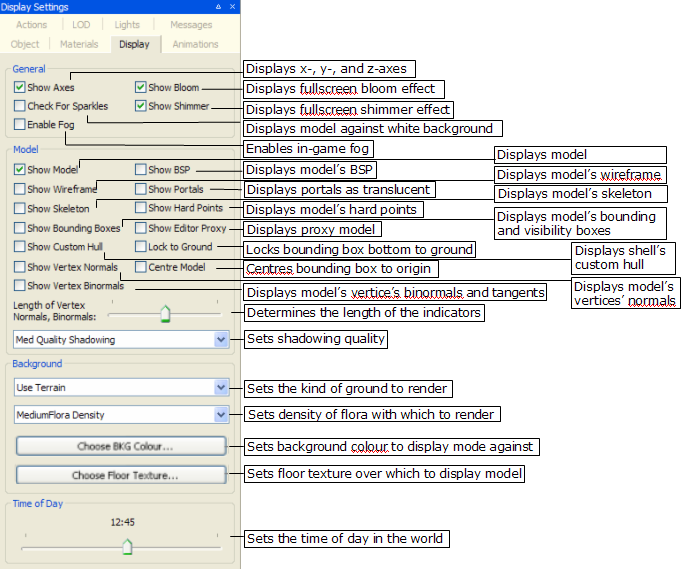
Display Settings panel
The list below describes the fields on this panel:
General
Show axes
Toggles rendering of the X-, Y-, and Z-axes.
Show bloom
Toggles the bloom full-screen effect.
Blooming is a way to simulate the high dynamic range of lighting, by producing an automatic glow around very bright objects.
Check for sparkles
Overrides all other display settings, and displays the model against a white background with white ambient lighting — this is used to highlight any seams in the model.
Sparkles along seams can occur when two separate models (e.g., a detachable arm a torso) are not properly joined. By rotating the model against a white background, any gaps along seams will sparkle.
Show shimmer
Toggles the shimmer full-screen effect.
Shimmer is a special effect that is suited to simulating the diffraction from a moving water surface or bubbles, and localised heat-haze effects.
This will have an effect in Model Editor only if the model has a shimmer material.
Enable Fog
Toggles in-game fog.
Fog is particularly useful when dealing with sky domes.
Model
Show model
Toggles rendering of the model. In general, this option will be cleared only when the Show Skeleton check box is selected, to give the user a view only of the model's skeleton.
Show BSP
Toggles the display of model's BSP, which is used to calculate the collision scene.
Note
Skinned objects do not have an associated BSP tree, unless a custom one has been exported with it.
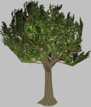
Show BSP—OFF
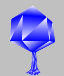
Show BSP—ON
Show wireframe
Toggles the display of the model as a mesh.
Show Wireframe—OFF
Show Wireframe—ON
Show portals
Toggles the display of portals as a translucent blue region.
This option is applicable only to shells.

Show Portals—OFF
Show Portals—ON
Show skeleton
Toggles the display of model's skeleton, which will be rendered over the model itself.
It is possible to show only the skeleton by clearing the Show Model check box.

Show Skeleton—OFF
Show Skeleton—ON
Show hard points
Toggles the display of model's hard points — each will be rendered alongside its name and XYZ axes.
For details on hard points, see the document Client Programming Guide's section Models → Hard Points.

Show Hard Points—OFF
Show Hard Points—ON
Show bounding boxes
Toggles the visibility of model's bounding box (yellow) and visibility box (blue).
Performs the same function as the Display Bounding Box (
) toolbar button — for details, see Toolbar.Show editor proxy
Toggles the display of the proxy model (specified in the Object Properties panel's Editor Proxy Model field) alongside the current model.
For details on proxy models, see Object Properties panel.
Show custom hull
Toggles the display of shell's custom hull defined in the .visual file (for details on this file's grammar, see the document File Grammar Guide's section .visual).
This option has no effect on shells that do not define a custom hull.
This option is applicable only to shells.
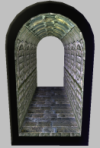
Show Custom Hull—OFF
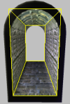
Show Custom Hull—ON
Show vertex normals
Toggles the display of normals for each of the model's vertices, which will be rendered in yellow.

Show Vertex Normals—OFF
Show Vertex Normals—ON
Centre model
Centres the model's bounding box at the origin.
Show vertex binormals
Toggles the display of binormals for each of the model's vertices — tangents will be rendered in red, and bi-normals in blue.

Show Vertex Binormals—OFF
Show Vertex Binormals—ON
Length of vertex normals, binormals
Specifies the length of the in which the vertices' normal, bi-normals, and tangents will be displayed.
Low value for length
High value for length
Shadowing settings
Specifies the quality in which to render the model shadow.
The higher the quality of the shadowing, the more CPU resources are used, thus decreasing the number of frames per second in which the model is rendered.
Note
If the Show Wireframe check box is selected, then Shadowing Settings will have no effect on the model.

Disabled

Low quality

Medium quality

High quality
Background
Background option
Specifies what kind of ground should be rendered with the model:
No background
Only the model will be rendered, with no floor or terrain.
Use floor
The model will be rendered on top of the floor texture specified via the Choose Floor Texture button.
Use terrain
The model will be rendered against the terrain specified for the space used in Model Editor (this is set in bigworld/tools/modeleditor/options.xml file's space tag (for details on this file's grammar, see the document File Grammar Guide's section options.xml → World Editor).
Flora density option
Specifies the density of the flora to be rendered alongside terrain — this option is only available if the Background Option drop-down list box is set to Use Terrain.
Note
Settings for the flora — including its density — are specified in the flora.xml file (for details on this file's grammar, see the document File Grammar Guide's section
<flora>.xml) specified in the space's space.settings configuration file's flora tag (for details on this file's grammar, see the document File Grammar Guide's section space.settings).If the tag is not present, then Model Editor will use the settings specified in the flora.xml file specified in the resources.xml file's floraXML tag (for details, see the document Client Programming Guide's section Overview → Configuration files → File resources.xml.).
Choose BKG colour
Opens the Color dialog box, where you can specify the colour against which the models will be rendered.
The selected colour will be applied to the background only if the Background Option drop-down list box is set to No Background or Use Floor.
Choose floor texture
Opens the Open dialog box, where you can specify the image to be used as the floor texture.
Bitmaps, TGA, and JPG images can be used as a floor texture.
Note
Items can be dragged into this button from Asset Browser panel's Textures virtual folder — the dragged texture will be applied to the floor.
Note
The texture tiling size (which defaults to 1 metre) ins configurable via the bigworld/tools/modeleditor/options.xml file's settings/floorGrid tag
Time of day
Sets the current time of the day in the world.
Changing the time of day affects the angle of the sun, and hence it also affects:
Ground — depending on Background Option.
Shadow cast:
Upon the model — depending on Shadowing Setting.
On ground — depending on Shadowing Setting and Background Option.
As mentioned in the Shadowing Settings entry, if the Show Wireframe check box is selected, then shadows are not rendered.
If Background Option is set to Use Terrain, then the sky changes according to the time.
The table below describes how the ground is affected by this field:
Shadowing settings Background option No Background Use Floor Use Terrain Disable shadowing None. No ground is rendered. Floor is rendered more darkly or brightly, according to colour of the light. Terrain and sky are rendered according to colour of the light. Low quality Floor is rendered more darkly or brightly, according to angle of the sun. The model's shadow is cast on the ground according to angle of the sun. Terrain and sky are rendered according to angle of the sun. The model's shadow is cast on the ground according to angle of the sun. Medium quality High quality Note
The Lighting Setup panel also has a Time of Day slider (under the Game Lighting option button), which is automatically changed to the value set on this field. For details, see Lighting Setup panel.
This panel allows you to manipulate the animations exported from your 3D application
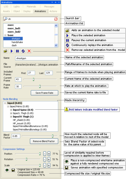
Animations panel
The list below describes the fields on this panel:
Search bar —

Restricts the animations displayed in Animation List to the ones containing the typed string.
The list is refreshed automatically as the string is typed.
The Clear button —
 — deletes the typed string, which causes the
Animation List to display all
animations associated to the model.
— deletes the typed string, which causes the
Animation List to display all
animations associated to the model.Animation list
List of all animations defined for each LOD of the model, which is set in the Level Of Detail panel (for details, see Level Of Detail panel).
Animations are listed in the order in which they were added to the model — which also will be reflected in the model file (for details on this file's grammar, see the document File Grammar Guide's section .model).
Animation buttons

Opens the Open dialog box, where you can specify an animation file (.animation) to associate to the selected model.

Plays the selected animation.

Pauses the current animation.

Continuously replays the current animation.

Dissociates the selected animation from the model. No confirmation is requested for this operation.
Name
Name of the selected animation.
Changes made to this field are automatically reflected in the Animation List list box.
File source
Path/filename of the selected animation.
The path is relative to one of the entries in the resources folders list (or
<res>). For details on how BigWorld compiles this list, see Starting the Tools.Included frames
Range of frames to include when playing the animation
Current frame
Number of the frame currently displayed.
As you move the slider, the frame in the viewport is automatically updated, according to the current settings for node blending.
Frame rate
Rate at which to play the animation.
Value ranges from 1 to 60.
Save frame rate
Writes the current value of Frame Rate to the model.
When viewing different animations, the modified value of Frame Rate is lost, unless it is written to the model.
Node blending
This panel allows the user to modify the settings that refer to animation node blending. Blend Factor determines the percentage of current node animation that will be retained when this animation is blended with another one.
Changes to node blending are saved in the model file, not in the original animation.
Node hierarchy
Displays the model's nodes that must be manipulated in order to achieve the overall animation, as set in your 3D application.
For each node, the following is displayed:
Node name.
Amount of node blending.
Blend factor
Sets the percentage of current node animation to retain when blending this animation with another one.
This value is specified in relation to the animation's original value set in your 3D application.
Value ranges from 0.0 to 1.0, with the effects described below:
0.0
None of the animation for the current node will be used in the final blended animation — i.e., the node will be moved as specified in the other animation.
Between 0.0 and 1.0
The specified percentage of the animation for the current node will be used in the final blended animation.
1.0
The animation for the current node will be used in the final blended animation as it is — i.e., none of the other animation will be used for current node.
Blend values greater than 1.0 can be assigned to a node to give it more weight when blending, but it is important to recognise that strong node blend values will effect the blend in and blend out times between actions. In the diagram below a node with a strong blend weight in Action A will still be the strongest influece at the time marker
 , if blending with a significantly less
weighty node.
, if blending with a significantly less
weighty node.
Remove blend factor
Sets Blend Factor of the selected node to same value of its parent node.
Compression settings
Group of settings that specify how much the animation should be compressed.
The key frames of an animation contain rotation, scale and position information. If this information does not change much over several frames, the intermediate frames (or inter frames) can have that information stripped out to save memory.
The sliders can be used to specify the threshold of similarity that determines whether to strip out the values for the inter frames. When changing the value of one of the sliders, it will only update when you release the left mouse button. Holding down shift while changing the slider will cause it to update every frame.
Position, Rotation, Scale
Required level of similarity in position/rotation/scale information before compression is applied to inter frames.

Produces a non-compressed wireframe animation of the model, played along a fully-rendered compressed one.
This way, the user can tweak the animation to achieve the best relation between animation quality and file size.
Preview

Saves the animation with the specified compression.
Compressed vs. Original file size
Displays the animation file size reflecting the current compression settings, against the current animation file size.
This panel allows you to create actions for the model, which can be used in scripts, and which are used by Action Matcher to determine the model's animations.
It also allows you to preview blending between actions that are on the same track and those that are on separate tracks. Model Editor has a set of rules in order to mimic the way the Action Matcher chooses how actions behave with each other in the game, these rules are:
If the action has no action match settings then it will be played once unless the Looped option is set.
If the action has trigger conditions then it will loop unless it has cancel conditions.
If the One Shot option is set then it will play once.
For details on match triggers and capability flags, see:
document Client Programming Guide's section Scripting → Functional components → Action Matcher.
document File Grammar Guide's section .model.
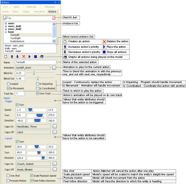
Actions panel
The list below describes the fields on this panel:
Search bar —

Restricts the actions displayed in Action List to the ones containing the typed string.
The list is refreshed automatically as the string is typed.
The Clear button —
 — deletes the typed string, which causes the
Action List to display all actions
associated to the model.
— deletes the typed string, which causes the
Action List to display all actions
associated to the model.Action list
List of all actions defined for each LOD of the model, which is set in the Level Of Detail panel (for details, see Level Of Detail panel).
Actions are listed in the order in which they were added to the model — which also will be reflected in the model file (for details on this file's grammar, see the document File Grammar Guide's section .model).
Most recent actions list
List of the three most recent used actions.
Action buttons

Opens the Create Action dialog box (for details, see Create Action dialog box), where you can specify an animation file (.animation) to associate to the new action.
The action is added directly after the selected action.

Increases the priority of the selected action

Decreases the priority of the selected action

Deletes the select action. No confirmation is requested for this operation.

Triggers the selected action.

Stops all actions currently playing.

Graphs on the viewport all actions being played on the model, with their respective blend weights.
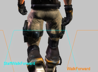
Graph with the actions being played on model, with their respective blend weights
Please note that this graph can also be displayed in-game using the Python console (for details, see the document Content Creation Manual's lesson Modify Animations With Actions → Debugging Animations, and the document Client Programming Guide's section Scripting → Functional components → Action Matcher → Debugging animations).
Name
Name of the action as used by a script.
These are available as named 'constants' of the model object returned by the Model Manager.
Changes to this field are automatically reflected in Action List list box.
Note
This has to be a Python-safe name, i.e., with only alphanumerics and the underscore character. Hence, it cannot support non-ASCII character sets, such as Chinese.
Animation
Animation to be played for the current action.
The Browse button —
 — opens the Choose
Animation dialog box (for details, see Choose Animation dialog box), where you can
select an animation file (.animation) for the
action.
— opens the Choose
Animation dialog box (for details, see Choose Animation dialog box), where you can
select an animation file (.animation) for the
action.Blend in
Time (in seconds ) to blend this animation in with the previous one.
Blend out
Time (in seconds) to blend this animation out with the next one.
Looped
Toggles the continuous replay of the selected action.
Is impacting
Sets whether the movement in the root node of the animation should be promoted to impact on the controlling entity's position (assuming it is being controlled by an entity).
When this check box is selected, the offset of the root node in each frame of the animation from the position of the root node in the first frame is recorded, then subtracted from that frame.
This should be used for an irregular movement like 'jump over a log', where the model position change due to the animation should actually change the entity's position (and where the functionality provided by Is Movement is not appropriate).
The offset of the final frame is available to scripts.
Note that changes to the entity's position caused by impacting actions do not consider the collision scene. Care should be taken to ensure that applying an impacting action does not result in the entity being stuck in the collision scene.
Is movement
Sets whether the animation contains built-in movement, such as a walk cycle or a run cycle.
The change in transform of the root node from the beginning to end is recorded, then proportionally subtracted from each frame (i.e., if this check box is selected, then a run animation that does not run on the spot will appear to).
Since the subtraction is proportional to the frame number, if you move the model's transform at a constant speed, then the animation will play back exactly as it was exported, since the amount added by the movement of the transform will exactly match that subtracted from the movement of the root.
This check box should be selected for linear animations with regular movement. For irregular movements, select the Is Impacting check box instead.
IsMovement actions can also use the scale playback speed option.
The recorded offset of the last frame is available to scripts.
Is coordinated
Sets whether the animation is part of a sequence that is to be coordinated with a corresponding action on another model, and this animation does not start at the origin.
In this case, the offset of the root node in the first frame of the animation from the same node in its cognate animation's first frame is recorded, and subtracted completely from the root node for every frame of the animation (i.e., if this check box is selected, then the action for an animation that does not occur at the origin will play as if it did).
The offset from the cognate is available to scripts, so that models can be perfectly positioned and have their animations played back exactly as they were exported.
Note: The cognate animation is recorded in the animation definition, not in the action definition. The cognate is an animation whose root node in the first frame is in exactly the same pose as the root node in the first frame of the animation being described, except that the animation being described is offset from the origin — i.e., it is the normal (non-offset) animation that was being played immediately prior to the animation being defined. The 'idle' animation is almost always a suitable cognate for animations whose actions will be coordinated.
Track no.
Track on which the selected animation should be played.
A model may have different animations played on it at the same time, if each one is running on a different track.
Own track
Sets whether the action's animation should be played on its own track. An action with this field selected will have its animation always always blending with other animations playing at the same time.
Match
Group of conditions that must be met before Action Matcher triggers or cancels the selected action. For details on match triggers and capability flags, see the document Client Programming Guide's section Scripting → Functional components → Action Matcher, and the document File Grammar Guide's section .model.
Trigger
Group of conditions that must be met for the Action Matcher to trigger the action.
Falling (check box)
Determines whether the model must be falling in order for the action to match.
If this option is selected, then Speed is interpreted as the falling velocity. To further clarify, if the minimum and maximum velocities are set to 1 and 20 m/s then without falling being selected the action will be matched by a horizontal or vertical speed between 1 and 20 m/s. If falling is selected, then the action will be matched by a negative vertical velocity between 1 and 20 m/s.
Speed
Minimum and maximum entity speeds.
If the Falling check box is selected, then this is the vertical falling velocity.
Turn
Minimum and maximum difference between entity's head and body angle.
Direction
Minimum and maximum yaw of the model in relation to the entity.
Caps onA
List of user-defined capability flags that should be on.
Caps offA
List of user-defined capability flags that should be off.
Cancel
Group of conditions that must be met for the Action Matcher to cancel the action.
Turn (check box), Speed, Turn, Direction, Caps onA, Caps offA
Same as Trigger.
One shot
Indicates to Action Matcher that the action should cancel the triggered action after playing it once.
Scale playback speed
Indicates that the speed at which the action is played should be scaled, in order to match the straight-line speed of the entity.
It is used to keep the feet from sliding along the ground, while allowing the entity to move at any pace.
Promote motion
Indicates that a model should inherit the movement from an action, instead of blending out its movement back to the origin once it has finished playing.
Also indicates, for any client-controlled entity (such as the Player), that the entity will inherit the Action's translation. Note that any rotation in such actions will not be promoted to the Entity, only to the Model.
Note that this option should always be turned on for IsImpacting and IsMovement actions, or else those options will not work correctly.
Feet follow direction
Indicates that the model should face the direction to which the entity is heading.
This will be a temporary change, and the model will blend back to pointing 'straight ahead' after the action has finished playing.
A — The Browse
button —— opens the Action
Triggers dialog box, where you can specify the list of
capabilities that will affect triggering the action. For details, see
Action Triggers dialog box.
This dialog box is invoked by Actions panel's New
Action button ——, and allows you to create an action for the
selected model.
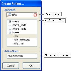
Create Action dialog box
The list below describes the fields on this dialog box:
Search bar —
Restricts the animations displayed in the Animation List to the ones containing the typed string.
The list is refreshed automatically as the string is typed.
The Clear button —
— deletes the typed string, which causes the
Animation List to display all animations associated to the
model.Animation list
List of all animations defined for each LOD of the model (set in the Level of Detail panel).
Animations are listed in the order in which they were added to the model — which also will be reflected in the model file (for details on this file's grammar, see the document File Grammar Guide's section .model).
Note
The specified animation might belong to a model different from the one selected in the Actions panel.
Action name
Name of the new action.
Note
This has to be a Python-safe name, i.e., with only alphanumerics and the underscore character. As a consequence, it cannot support non-ASCII character sets, such as Chinese.
Cancel
Closes the dialog box without creating an action.
OK
Closes the dialog box, updating Actions panel's Name and Animation fields with the specified values.
This dialog box is invoked by the Animation field's Browse button — —, and allows the user to choose the animation to be associated with the selected action.
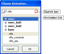
Choose Animation dialog box
The list below describes the fields on this dialog box:
Search bar —
Restricts the animations displayed in the Animation List to the ones containing the typed string.
The list is refreshed automatically as the string is typed.
The Clear button —
— deletes the typed string, which causes the
Animation List to display all
animations associated to the model.Animation list
List of all animations defined for each LOD of the model (set in the Level Of Detail panel).
Animations are listed in the order in which they were added to the model — which also will be reflected in the model file (for details on this file's grammar, see the document File Grammar Guide's section .model).
Note
The specified animation might belong to a model different from the one selected in the Actions panel.
Cancel
Closes the dialog box without assigning an animation to the selected action.
OK
Closes the dialog box, updating Actions panel's Animation field with the selected animation.
This dialog box is invoked by the Actions panel's various Browse buttons —— on the Capabilities fields, and allows the user to
specify the capabilities that must be on (if the dialog box was
invoked from Caps On) or off (if
invoked from Caps Off) for the action
to be triggered (if invoked from the Trigger section) or cancelled (if invoked from
the Cancel section).
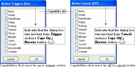
Action Triggers dialog box
The illustration below shows the effect of the selected capabilities in the current action, according to the button that invoked the dialog box:
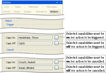
Example
The list below describes the fields on this dialog box:
Capability list
List is retrieved from fantasydemo/res/scripts/common/capabilities.xml.
For details on this file, see the document File Grammar Guide's section capabilities.xml.
Cancel
Closes the dialog box without assigning any capabilities to the invoking field.
OK
Closes the dialog box, updating the invoking field with list of selected capabilities.
This panel allows the user to set discrete levels of detail for the model, and to specify the distances at which to use them.
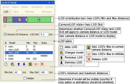
Level Of Detail panel
The list below describes the fields on this panel:
LOD distance bar
Graphic representation of LOD levels.
The bar is divided into ranges, one for each entry in the LOD table. The ranges are displayed in proportion to the distances they cover.
Min and Max columns in the LOD Table are automatically updated according to changes made to the bar.
Camera/LOD slider
Sets LOD Dist.
Virtual LOD distance
Determines whether Camera/LOD slider and LOD Dist will affect the LOD model displayed (if the check box is selected), or camera distance (if the check box is cleared).
LOD Dist
Depending on the value of Virtual LOD Distance check box, it has the following behaviour:
If selected:
Displays the LOD model associated to that distance.
If cleared:
Sets the camera distance to the model.
LOD table
Contains one row for each LOD level.
It contains the following fields:
#
Sequential number of the LOD.
Model
Model to be drawn for the LOD.
Min
Minimum distance from the camera for which the model will be drawn.
If the model moves closer to the camera, then the model specified for the previous LOD will be drawn.
This field can be set by the LOD Distance Bar, the Promote LOD button —
 —, the Demote
LOD button —
—, the Demote
LOD button — —, and the Min
Dist field.
—, and the Min
Dist field.Min column of the first non-hidden LOD can only be 0.
Max
Maximum distance from camera in which model will still be drawn.
If the model moves closer to the camera, then the model specified for the next LOD (if any) will be drawn.
If an ellipsis is displayed in this column, it means that the LOD has no maximum range — this is done via Set To Infinite —
 — button.
This field can be set by the LOD Distance Bar, the Promote LOD button —
—, the Demote
LOD button ——, the Apply Camera
Distance button — —, the Set to
Infinite button ——, and the Max
Dist field.
—, the Set to
Infinite button ——, and the Max
Dist field.State
Determines whether the model should be actually rendered at any point.
An LOD might be set as hidden (via the check box with the same name), in case we want other LODs to inherit its animations and/or actions, but do not want it to be rendered at any distance.
If an LOD model cannot be located, then its State will be set to Missing — in this case, the model can be changed to a valid one by using the Change Model button —
 —.
—.
LOD table buttons

Opens the Open dialog box, where the user can specify a model file (.model) to be associated to the new LOD added at the end of LOD Table.
New LOD's Min column will be set to the value of previous LOD's Max column, or to previous LOD's Min column plus 10 metres, in case its Max is set to … (infinite).
New LOD's Max column will be set to … (infinite).
Opens the Open file dialog box, where the user can specify a new model file (.model) to replace the remainder of the LOD trunk from the selected LOD down the tree. Note: This may change multiple models in the tree.
Moves the selected LOD to the row above.
This causes the selected model to swap values of Min and Max columns with the LOD that previously occupied the row above.
This button will be disabled if the first or the second LOD is selected (in the latter case, that is because it would make the current model to change).
Moves the selected LOD to the row below.
This causes the selected model to swap values of Min and Max columns with the LOD that previously occupied the row below.
This button will be disabled if the first or the last LOD is selected.
Sets Max column of the selected LOD to current camera distance.
Sets Max column of selected LOD to … (infinite).
The value of State column of LODs below the selected one are automatically changed to Hidden.

Removes the selected LOD.
The value of Max column of the first non-hidden LOD above the selected one will be automatically changed to the value of Min column of the selected LOD.
If only one LOD is left after pressing this button (which means that now the model has no effective LOD, and only the current model is listed in the LOD table), then the value of its Max column is set to … (infinite).
This button will be disabled if the first LOD is selected.
Min Dist
Sets Min column of LOD table's selected LOD.
Max Dist
Sets Max column of LOD table's selected LOD.
Hidden
Sets State column of LOD table's selected LOD.
This panel lets the user change the current lighting settings in Model Editor.
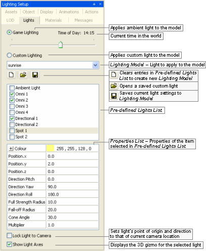
Lighting Setup panel
The list below describes the fields on this panel:
Type of light
Game lighting
Applies ambient light to the model.
Time of dayA
Sets the current time of day in the world.
Note
The Display Settings panel also has a Time of Day slider, which is automatically changed to the value set on this field — for details, see Display Settings panel.
Custom lighting
Applies custom light to the model.
Lighting modelB
Saved custom Model Editor Lighting Model (.mvl)C applied to the model.
Lighting model buttonsB

Clears values specified in the Pre-defined Lights List, in order to create a new Lighting Model.

Opens the Open dialog box, where you can specify a Model Editor Lighting Model (.mvl)C file to apply to the model.

Opens the Save As dialog box, where you can specify a Model Editor Lighting Model (.mvl)C file to save the current light settings to.
Pre-defined lights listB
List of instances of light types that might be applied to the model.
The selected light instances will be applied to the model, and each can be configured in the Properties List list box.
Each Lighting Model might have the following light types (described in the order they appear in the list box):
Ambient (1 instance)
Covers the entire scene with omnidirectional light.
Omni (4 instances)
Radiates from a three-dimensional point, giving more control over the concentration of light in certain areas.
It is done by specifying an area of full light intensity, and a bigger area in which light gradually fades away.
Directional (2instances)
Directs a wide area of radiance at a particular area or object — ideal for simulating infinite-point light sources, such as sunlight, moonlight, and firelight. The first directional light is used for determining the shadow angle, if it is enabled.
Shadows are enabled in the Display Settings panel's Model group box's Shadowing Settings drop-down list box (for details, see Display Settings panel).
Spot (2 instances)
Produces a small, concentrated, and directed source of light — ideal for illuminating small details in the scene, or for simulating street lights and torches.
Properties listB
List of properties relative to the light instance selected in Pre-defined Lights List.
The list varies according to the type of light, as described in the list below:
Colour (available for Ambient, Directional, Omni, and Spot)
Light's colour and alpha value, in RGB values. The Browse button —
 — opens the Color dialog box.
Cone angleD (available for Spot)
Angle of the cone of light generated by spot light.
The angle at which the light is placed in relation to the ground or to the model affects its intensity.
Direction pitchD, Direction rollD, Direction yawD (available for Directional)
Direction in which the light will be projected.
It can be automatically set if the Lock Light To Camera check box is selected.
Full strength radius (available for Omni and Spot)
Area over which the light will be at full intensity.
Fall-off radius (available for Omni and Spot)
Total area influenced by the light.
The area starting at Full Strength Radius will have light at full intensity, which will be faded away until it is completely off when it reaches Fall-off Radius.
Position XD, Position YD, Position ZD (available for Omni and Spot)
Light's point of origin.
It can be automatically set if the Lock Light To Camera check box is selected.
These fields may be changed by the axis gizmo displayed by the Show Light Models check box.
Multiplier (available for Directional, Omni, and Spot)
Multiplier for the colour's RGB value, which affects the overall luminosity of the light without affecting its hue.
The RGB values will be multiplied by this value, effectively making the light brighter.
Lock light to camera
Attaches the current camera position to the following fields:
For directional and spot lights:
Direction Pitch, Direction Roll, and Direction Yaw.
For omni and spot lights:
Position X, Position Y, and Position Z.
Once the light is in the position you want, clear this option to detach the camera.
Show light axesD
Displays a gizmo representing the light source. Meaningful only for omni and spot lights.
A — Only enabled if the Game Lighting option button is selected.
B — Only enabled if the Custom Lighting option button is selected.
C — For details on this file's grammar, see the document File Grammar Guide's section .mvl)
D — If the Show Light Axes check box is selected, then the gizmo (in conjunction with key modifiers) can be used to change some of the light's fields. For details, see Key modifiers.
Some properties can be changed in Model Editor, as defined in the FX file. For more details, see the document Client Programming Guide's section 3D Engine (Moo) →EffectMaterial → Automatic variables/Globals.
Each material file has its own list of properties. For a broader discussion of these settings, please refer to the document Content Creation Manual (document accessed by pressing F1 or by selecting the Help → Content Creation menu item — for details, see Menu items).
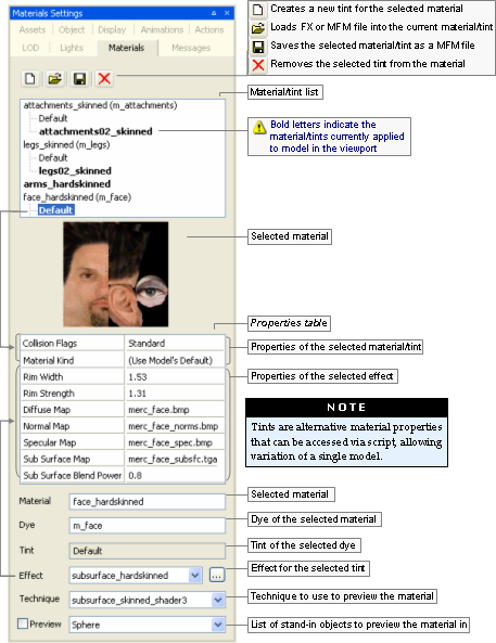
Materials Settings panel
The list below describes the fields on this panel:
Material/ tint list buttons

Opens the New Tint dialog box, where you can specify a name and a material (.mfm) or effect (.fx) file for the tint to be applied to the material.
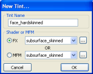
New Tint dialog box

Opens the Open dialog box, where you can select a new material (.mfm) or effect (.fx) file for the selected tint.
The Effect drop-down list box is updated with the value selected in the dialog box.

Opens the Save As dialog box, where you can save the settings of selected material/tint as new material (.mfm) file.

Removes the selected tint — no confirmation is asked.
This button is disabled to Default tints.
Material/ tint list
List of materials/tints associated with the model.
Altering the material on the model and saving it creates a new instance of this material to be saved within the model's .visual file (for details on this files' grammar, see the document File Grammar Guide's section .visual). Therefore, the model will no longer reference the MFM file.
Note
Skinned objects in which each point can be affected by up to three bones will have the suffix _skinned appended to its material name.
Properties table
Due to its extents, this table is discussed on a section of it own.
Please refer to Material Properties table.
Note
Items can be dragged into this table from the Effects and Texture folders in the Asset Browser panel. This will result in changing the Effect drop-down list box.
Material
Name of the material.
For details, see Default Material Kind and Material Kind in Textures.
Dye
Name of the dye.
It defaults to the material name, prefixed by m_.
Note
This needs to be a Python-safe name, i.e., with only alphanumerics and the underscore character. As a consequence, it cannot support non-ASCII character sets, such as Chinese.
Tint
Name of the tint.
Every material with a tint will have one named Default, which name cannot be changed.
Effect
Effect to be applied to selected material/tint.
The Browse button —
 — opens the Open dialog box, where you can
select an effect (.fx) file for the selected material/tint.
— opens the Open dialog box, where you can
select an effect (.fx) file for the selected material/tint.Note
Items can be dragged into this field from the Effects virtual folder in the Asset Browser panel.
Technique
Technique to use to preview the material.
This allows the preview of different fallback rendering techniques offered by the material's shader. It would mainly be used for the debugging of shaders, allowing their fallback techniques to be tested.
Preview
List of stand-in objects to preview the material in. The check box next to the field toggles the preview function.
The available options are:
Sphere
Cube
Room
Torus
Teapot
The first 2 rows of the table (Collision Flags and Material Kind) are fixed, and list properties specific to the material/tint selected in the Material/tint List list box. Subsequent rows are variable, and list the properties of the Effect drop-down list box.
The list below lists the rows relative to the selected material/tint:
Collision flag
Used to specifies whether the camera and/or player collide with surfaces of this material.
Camera Off Player Off — Neither the camera nor the player collide with the material.
Camera Off Player On — The player will collide with the material, while the camera will not.
Camera On Player Off — The camera will collide with the material, while the player will not.
Camera On Player On — Both the camera and the player will collide with the material.
Note
If either the camera or the player collide with the material, the material will cast terrain shadows.
Note
Models with custom BSP trees will not be affected by changes in the collision flag — you will have to re-export the model with either a different custom BSP, or none (depending on your purpose) from your 3D package.
For details on how to create custom BSP trees, see the document Content Creation Manual's lesson Create Custom BSPs (document accessed by pressing F1 or by selecting the Help → Content Creation menu item — for details, see Menu items).
Material kind
Material kind for the model (such as wood, glass, etc...), used to define sounds and particle systems to objects.
For details on Default Material Kind and Material Kind, see Textures.
The list below describes the most common properties for the effect:
Alpha reference
The cut-off value at which the texture's alpha channel will determine the transparency.
Range of values is from 0 through 255. Setting this field to 200 would cause areas of the image with an alpha value smaller than 200 to be transparent, and all others as solid.
Alpha text
Determines whether the alpha map of the material should be used.
Diffuse light extra modulation
Value to multiply the diffuse map by.
Diffuse mapA
Base texture map.
Double sided
Indicates whether the material can be seen from both sides.
Light enable
Indicates whether the material will receive lighting.
If set to false, then the texture's original colour will be displayed.
Other mapA
Texture map to roll across the surface.
Self illumination
Intensity with which the material should be illuminated as if it was a light source.
Specular mapA
Texture map specifying specularity for the material.
Normal mapA
Normal map to use for the material.
For details on normal maps, see the document Content Creation Manual's lesson Build and Use Normal Maps (document accessed by pressing F1 or by selecting the Help → Content Creation menu item — for details, see Menu items).
A — Texture maps can be assigned a texture feed — for details, see Texture map context menu. The name of the texture feed is displayed between parentheses, next to the texture description.
Accessed by right-clicking any texture map in the Materials Settings panel's Properties Table, the context menu contains the following items:
Enable texture feedA
Allows you to specify a name for the texture feed to be assigned to the texture map.
Change texture feed nameA
Allows you to change the name of the texture feed assigned to the texture map.
Remove texture feedA
Allows you to remove the texture feed assigned to the texture map.
A — Opens the Texture Feed Name dialog box — for details, see Texture Feed Name dialog box.
Any non-default tint material can have its Vector4 properties (such as Colour) exposed, so that they can be accessed through Python scripts during runtime.
In order to do this, access the context menu of the Vector property of a non-default tint by right-clicking it, then select the Expose To Python menu item:
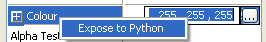
Exposing a property to Python — Step 1
Note
When a property is exposed to Python, its exposed name is displayed in the material properties description. It will be the UIName given in the shader — this is the name exposed to Python.
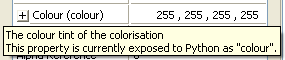
Exposing a property to Python — Step 2
In order to unexpose the material property, access the context menu of the Vector property by right-clicking it, then select Hide From Python menu item:
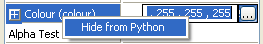
Exposing a property to Python — Step 3
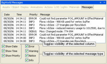
The split lens effect from the sun will be used automatically for any material with the following settings:
('Sorted' Render Channel OR 'Alpha Test Enabled') AND SrcBlend == src alpha AND DestBlend == inv src alphaThe old .bsp file has to be deleted before your changes can be displayed in the BigWorld project. The .bsp file is generated by BigWorld to speed startup in subsequent sessions.
Table of Contents
The Particle Editor is a component of the BigWorld toolset that provides a graphical interface for the creation of a BW particle system XML file.
BigWorld particle systems can be defined in three ways:
C coding.
Python scripting.
XML file.
Once the particle system is created, the game script can load the XML file and place an instance of a particle system in the game world. This can be done in two ways:
As part of the scenery
By placing a particle object in World Editor (a ChunkParticles chunk item).
As a dynamic entity
Through Python scripting or C coding. For details, see Loading a particle system via code.
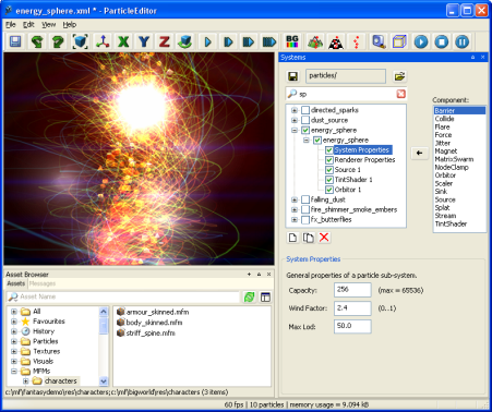
Particle Editor window
For details on how to start this and other BigWorld tools, see Starting the Tools.
The list below describes the menu items available in Particle Editor:
File → Open particle directory
Performs the same function as the General sub-panel's Open Particle Folder buttonA —
 —.
—.File → Save particle system
Performs the same function as Systems panel's Save buttonA —
 — and Save
toolbar buttonB —
— and Save
toolbar buttonB — —.
—.File → Reload all textures
Reloads textures used by the particle system.
Changes made to textures in third-party applications will not be visible until the particle system is reloaded or this option is selected.
File → Exit
Closes the application.
The user will be prompted to save any changes made to the scene.
Edit → Undo
Undoes the most recent action.
Multiple actions can be undone. The undo list extends to the state of the world when Particle Editor was last started.
Each action undone is added to the redo list.
Also accessible via the Undo toolbar buttonB —
 —.
—.Edit → Redo
Redoes the most recent undone action.
Multiple actions can be redone. The redo list contains one entry for each undone action.
Also accessible via the Redo toolbar buttonB —
—.View → Toolbars → Main ToolbarB
Toggles the toolbar's visibility.
View → Status bar
Toggles the status bar's visibility.
For details on the status bar, see Status bar.
View → Show Action Selection
Toggles the visibility of all panels.C
View → Show Asset Browser
Toggles the visibility of the Asset Browser panel (for details on this panel, see Asset Browser panel).
View → Show Messages
Toggles the visibility of the Messages panel (for details on this panel, see BigWorld Messages panel).
View → Load default panel layoutA
Closes all customised panels and displays Particle Editor's default panel.A
View → Load most recent panel layoutA
Closes all current panels and displays the custom panel layout previously used.A
Languages → List of available languages
Selects the language to use in the tool.
This list is compiled based on the LanguageName tags present in the XML files in the
<res>/helpers/languages folder and in the file pointed by the language tag in bigworld/tools/particleeditor/options.xml.Help → About Particle Editor
Opens the Particle Editor version dialog box.
Help → Tools Reference Guide
Opens this document.
Help → Content creation
Opens the document Content Creation Manual.
Help → Shortcuts
Opens the Particle Editor Shortcuts dialog box.
For details, see Particle Editor Shortcuts dialog box.
Help → Request feature/report bug
Opens your e-mail program, with the To: field automatically set to BigWorld's support e-mail address, and Subject: set to Particle Editor — Feature Request / Bug Report.
A — For details, see General sub-panel.
B — For details, see Toolbar.
C — For details on the panel system and its terminology, see Panel System.
The list below describes the toolbar buttons available in Particle Editor:
- — Save
Saves the current particle system.
Performs the same function as the File → Save Particle System menu item.A
- — Undo
Undoes the most recent action.
Performs the same function as the Edit → Undo menu item.A
 — Redo
Redoes the most recent undone action.
Performs the same function as the Edit → Redo menu item.A
 — Zoom to
extents
— Zoom to
extentsMoves the camera so that the model is brought to the centre of the screen.
This is useful if you have moved the camera far away from the model.
 — Free
positioning
— Free
positioningSets camera movement to a swivel action.
 —
X-locked
—
X-lockedLocks camera movement to the x-axis.
 —
Y-locked
—
Y-lockedLocks camera movement to the y-axis.
 —
Z-locked
—
Z-lockedLocks camera movement to the z-axis.
 — Orbit
camera
— Orbit
cameraToggles the rotation of the camera around the geometric centre of the model.
You can change the orbit direction by pressing d (clockwise camera rotation) and a (counter-clockwise camera rotation).
ON
Camera rotates around the model in a circle.
OFF
Camera ceases rotation, keeping its last position.
 — Slow,
 — Medium,
 — Fast,
 — Super
fast
— Super
fastSpecifies how fast the camera travels in response to the appropriate key events (keys Q, W, E, A, S, and D).A
If Caps Lock is on, then camera speed will be boosted.
Camera speed can also be set to Slow, Medium, Fast and Super Fast by the keyboard shortcuts Ctrl+1, Ctrl+2, Ctrl+3, and Ctrl+4, respectively.
 — Background
colour
— Background
colourOpens the Colour Picker dialog box, where you can change the background colour on the viewport.
 — Use terrain as
background
— Use terrain as
backgroundDisplays the particle system against the terrain specified in the tool's configuration file B.
 — Use floor as
background
— Use floor as
backgroundDisplays the particle system against the generic floor image.
The floor image file is specified in the tool's configuration fileB.
 — Use no
background
— Use no
backgroundDisplays the particle system against the background colour specified via the Background Colour toolbar button.
 — Toggle
grid
— Toggle
gridToggles the visibility of a 1mx1m grid, displayed against the particle system.
 — Toggle bounding
box
— Toggle bounding
boxToggles the visibility of the particle system's bounding box (yellow) and visibility box (blue).
 — Play
Plays the current particle system.
 — Stop
Stops the current particle system.
 — Pause
Cycles between pausing and resuming the current particle system.
A — For details, see Keyboard shortcuts.
B — The Particle Editor's configuration file is bigworld/tools/particleeditor/options.xml. For details on this file's grammar, see the document File Grammar Guide's section options.xml → Particle Editor.
The status bar displays information about the current particle system. A typical status bar is illustrated below:

Status bar
The list below lists the pieces of information displayed in the status bar, as they appear:
Frame rate (in the example, 64 fps)
Frame rate being used to display the particle system.
Particles displayed (in the example, 66 particles)
Number of particles being currently rendered.
This number varies along the lifetime of the system.
Memory used (in the example, memory usage = 3.5552 kB)
Memory used by the current particle system.
The movement and scale gizmos availability depends on the sub-system's component selected in the Particle's sub-systems list box, as described in the sections below.
Displayed if one of the sub-system's components below is selected in the Particle's sub-systems list box:
Barrier
Depending on the Barrier Shape drop-down list box.
Force
Orbitor
Source
One movement gizmo is displayed for the Initial Position Generator field, and another for the Initial Velocity Generator field. Each of these fields will have two movement gizmos if the Generator Type drop-down list box is set to either Cylinder or Line.
Stream
Movement gizmo
Activated by the Alt keyboard shortcut (for details, see Keyboard shortcuts) and represented by red and/or green circles, this gizmo allows a particle's component to be scaled. Dragging the circle inwards or outwards uniformly shrinks or enlarges the component, respectively.
This gizmo is displayed if one of the sub-system's components below is selected in the Particle's sub-systems list box:
Barrier
If Barrier Shape is set to Cylinder:
Red circle controlling Radius.
If Barrier Shape is set to Sphere:
Green circle controlling Radius.
Source
If Initial Position Generator or Initial Velocity Generator is set to Cylinder:
Red circle controlling Radius.
If Initial Position Generator or Initial Velocity Generator is set to Sphere:
Green circle controlling Minimum Radius and red circle controlling Maximum Radius.
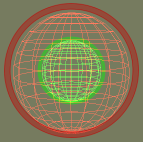
Scale gizmo
The list of Particle Editor's keyboard shortcuts can be displayed via the Help → Keyboard Shortcuts menu item (for details, see Menu items).
The sections below list the Particle Editor's keyboard shortcuts.
F1
Displays the help page, which can be left by pressing Esc.
F2
Allows renaming of the currently selected item in the Particle List.
F3
Performs the same function as the Play toolbar buttonA —
—.F4
Performs the same function as the Stop toolbar buttonA —
—.F5
Performs the same function as the Pause/Resume toolbar buttonA —
—.Ctrl+F5
Activates the Realtime Profiling console, which can be left by pressing Esc — for details, see Realtime Profiling console.
Ctrl+F7
Activates the Debug (Watcher) console, which can be left by pressing Esc — for details, see Debug (Watcher) console.
A — For details, see Toolbar.
Alt
If Debug (Watcher) consoleA is active
If key [0-9] in the alphanumeric keypad is pressed:
Selects item 40+[0-9], or 50+[0-9] (if Shift is pressed).
Ctrl
If clicking on a particle's sub-system check box
Causes all other sub-systems to acquire the opposite value of the current sub-system.
Particle's sub-system check boxes
If Debug (Watcher) consoleA is active
If key [0-9] in the alphanumeric keypad is pressed:
Selects item 20+[0-9], or 30+[0-9] (if Shift is pressed).
Shift
If Debug (Watcher) consoleA is active If key [0-9] in the alphanumeric keypad is pressed:
Selects item 10+[0-9], 30+[0-9] (if Ctrl is pressed), or 50+[0-9] (if Alt is pressed).
A — Activated by F7 (for details, see Debug (Watcher) console).
Backspace
If Debug (Watcher) consoleA is active:
Returns the list to the previous branch of the watcher tree.
Caps Lock
ON
Increases the current camera speed. It will accelerate the camera movement, which speed is set by keyboard shortcuts (Ctrl+1, Ctrl+2, Ctrl+3, and Ctrl+4), or by Camera Speed toolbar buttonsD (
,,, and ).OFF
Restores the camera speed set by keyboard shortcuts or by Camera Speed buttonsD.
Delete
Deletes the selected objects.
Enter
If Python consoleC is active and no command is specified:
Exits the console:
If Realtime Profiling consoleD is active
Expands or collapses the profiling element currently selected. Elements with children are indicated by an ellipsis (…) next to it.
If Debug (Watcher) consoleA is active
If the selected node is not leaf:
Navigates one level down in the watcher tree.
If the selected node is leaf:
Opens selected watcher for editing, or accepts typed value if it is already in Edit mode.
Esc
If any console is active
Exits the console.
NOTE: The different modes and consoles are activated in the following way:
Help mode — F1
Realtime profiling console — F5 (for details, see Realtime Profiling console)
Debug (Watchers) console — F7 (for details, see Debug (Watcher) console)
Python console — Ctrl+P (for details, see Python console)
If Debug (Watcher) consoleA is active
If the watcher is in Edit mode:
Leaves Edit mode.
If the watcher is not in Edit mode:
Exits the console.
Home
If Realtime Profiling consoleD is active
Scrolls the list to display the first page.
If Debug (Watcher) consoleA is active
Returns the list to root of the watcher tree.
Page Down
If Realtime Profiling consoleD is active:
Moves the selection to the next profiling element in the list. Same as ].
If Debug (Watcher) consoleA is active:
If the watcher is not in Edit mode:
Moves the selection to the next item in the list.
If the watcher is in Edit mode:
Decreases the watcher's value by 1, 10 (if Shift is pressed), 100 (if Ctrl is pressed), or 1,000 (if Alt is pressed).
A — Activated by F7 (for details, see Debug (Watcher) console).
B — For details, see Toolbar.
C — Activated by Ctrl+P (for details, see Python console).
D — Activated by F5 (for details, see Realtime Profiling console).
Numpad + (Plus sign)
If Realtime Profiling consoleB is active:
Scrolls the screen one line down.
If Debug (Watcher) consoleA is active:
Scrolls the watcher list down.
Numpad - (Minus sign)
If Realtime Profiling consoleB is active
Scrolls the screen one line up.
If Debug (Watcher) consoleB is active
Scrolls the watcher list up.
[ (Left square bracket)
If Realtime Profiling consoleB is active
Moves the selection to the previous profiling element in the list. Same as Page UpC.
] (Right square bracket)
If Realtime Profiling consoleB is active
Moves the selection to the next profiling element in the list. Same as Page DownC.
A — Activated by F7 (for details, see Debug (Watcher) console).
B — Activated by F5 (for details, see Realtime Profiling console).
C — For details, see Edit keys.
[0-9]
If Debug (Watcher) consoleA is active and the alphanumeric keypad was used:
Depending on the key modifier pressed (if any), selects the following item:
n10+
n(if Shift is pressed)20+
n(if Ctrl is pressed)30+
n(if Ctrl+Shift is pressed)40+
n(if Alt is pressed)50+
n(if Alt+Shift is pressed)
A — Activated by F7 (for details, see Debug (Watcher) console).
A
Moves the camera to the left.
If Orbit Camera toolbar buttonA —
— is selected:If the camera is rotating clockwise:
Stops the camera rotation.
If the camera is not rotating:
Rotate the camera counter-clockwise.
D
Moves the camera to the right.
If Orbit Camera toolbar buttonA —
— is selected:If the camera is rotating counter-clockwise:
Stops the camera rotation.
If the camera is not rotating:
Rotate the camera clockwise.
E
Moves the camera up.
G
If Realtime Profiling consoleB is active:
Draws a graph for the profiling element currently selected.
More than one element can be graphed at any one time. Each one will be assigned a different colour, which will be used to display the element's name, and draw the graph itself.
Q
Moves the camera down.
S
Moves the camera backwards.
W
Moves the camera forward.
A — For details, see Toolbar.
B — Activated by F5 (for details, see Realtime Profiling console).
Alt+Page Down
If Debug (Watcher) consoleA is active and the watcher is in Edit mode
Decreases the watcher's value by 1,000.
Alt+Page Up
If Debug (Watcher) consoleA is active and the watcher is in Edit mode
Increases the watcher's value by 1,000.
Alt+[0-9]
If Debug (Watcher) consoleA is active and used alphanumeric keypad
Selects list item 4[0-9].
Alt+Shift+[0-9]
If Debug (Watcher) consoleA is active and the alphanumeric keypad was used
Selects list item 5[0-9].
Ctrl+Page Down
If Debug (Watcher) consoleA is active and watcher is in Edit mode
Decreases the watcher's value by 100.
Ctrl+Page Up
If Debug (Watcher) consoleA is active and watcher is in Edit mode
Increases the watcher's value by 100.
Ctrl+[0-9]
Ctrl+1 turns the Slow Camera toolbar buttonB (
) on.Ctrl+2 turns the Medium Speed Camera toolbar buttonB (
) on.Ctrl+3 turns the Fast Camera toolbar buttonB (
) on.Ctrl+4 turns the Super Fast Camera toolbar buttonB (
) on.If Debug (Watcher) consoleA is active and used alphanumeric keypad
Selects item 2[0-9].
Ctrl+Shift+[0-9]
If Debug (Watcher) consoleA is active and used alphanumeric keypad
Selects item 3[0-9].
Ctrl+H
Accesses the View → Show Action Selection menu item.C
Ctrl+I
Cycles through the available camera speeds.
This value can also be set by the Camera Speed group of toolbar buttons —
,,,.Ctrl+M
Cycles through the available camera modes.
This value can also be set by the Camera Mode group of toolbar buttons —
,,,, .Ctrl+O
Accesses the File → Open Particle Directory menu item.C
Ctrl+P
Activates the Python console, which can be left by pressing Esc. For details, see Tools Consoles.
Ctrl+S
Accesses the File → Save menu item.C
Ctrl+T
Accesses the Edit → Reload All Textures menu item.C
Ctrl+Y
Accesses the Edit → Redo menu item.C
Ctrl+Z
Accesses Edit → Undo menu item.C
Note: The mouse cursor must be over the viewport for this shortcut to be enabled.
Shift+Alt+[0-9]
See entry Alt+Shift+[0-9] in this table.
Shift+Ctrl+[0-9]
See entry Ctrl+Shift+[0-9] in this table.
Shift+Enter
If Debug (Watcher) consoleA is active and watcher is in Edit mode
Displays the watcher modification history.
Shift+Page Down
If Debug (Watcher) consoleA is active and watcher is in Edit mode
Decreases the watcher's value by 1.
Shift+Page Up
If Debug (Watcher) consoleA is active and watcher is in Edit mode
Increases the watcher's value by 1.
A — Activated by F7 (for details, see Debug (Watcher) console).
B — For details, see Toolbar.
C — For details, see Menu items.
The list below describes the Particle Editor's mouse controls:
Right button drag
Moves the camera in the scene.
The table below describes the camera's movement:
Drag direction Camera movement Particle system movement Left Left Right Right Right Left Forward Up Down Backwards Down Up Scroll wheel rotate
Moves the camera forward and backwards.
If Space key is pressed:
Increases or decreases the camera speed, depending on the direction of the wheel rotation.
Performs the same functions as the
,,, and toolbar
buttons.C
Middle button click
Moves the camera so that the model is brought to the centre of the screen.
Performs the same function as the Zoom To Extents toolbar buttonA (
).
Particle systems need to be used with care, since they can easily have an adverse effect on the game's performance when targeting lower-end systems.
When designing the particle system, consider the points below:
Large particles may hinder performance (due to fill rate issues).
Each particle consumes memory, even if not being used (memory usage is shown in the status bar). Be sure to use a sink to remove unnecessary particles.
Set the the System Properties sub-panel's Capacity field to be just enough to contain the number of particles being used — this information is displayed in the status bar.
For details on the System Properties sub-panel, see System Properties sub-panel.
The Amp and Trail renderers on the Renderer Properties sub-panel need to cache each particle's history, and therefore consumes considerably more memory.
For details on the Renderer Properties sub-panel, see Renderer Properties sub-panel.
Use the System Properties sub-panel's Max LOD field to remove the particle from render once it reaches a certain distance from the player.
For details on the System Properties sub-panel, see System Properties sub-panel.
Accessed via the Help → Keyboard Shortcuts menu item, the Keyboard Shortcuts dialog box displays a list of shortcuts available on Particle Editor. For details on the complete list, see Keyboard shortcuts.
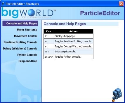
Keyboard Shortcuts dialog box
Assets used to populate the world can be accessed via the Asset Browser panel. For details, see Asset Browser panel.
This node gives you access to ambient particle systems created in Particle Editor, so you can place them in your world.
Note
For more information on particles, see:
document Client Programming Guide's section Particles.
document Content Creation Manual's lessons (document accessed by pressing F1 or by selecting the Help → Content Creation menu item — for details, see Menu items) lessons:
Manage Resources → Particles
Generate Particles for Special Effects
For details on the grammar of particle files, see the document
File Grammar Guide's section <particle>.xml.
This node gives access to bitmap images (.bmp), TrueVision Targa Graphic (.tga), and Microsoft Direct Surface (.dds) files, which can be assigned as the source for sprite-, amp-, trail-, and blur-based particles in the Renderer Properties sub-panel (for details on this panel, see Renderer Properties sub-panel).
This node gives access to visual files (.visual), which contain node hierarchy, vertices, indices, materials used for rendering objects, and the BSP tree used for collision detection.
Visual files can be assigned as the source for mesh-based particles in the Renderer Properties sub-panel (for details on this panel, see Renderer Properties sub-panel).
Note
For more information on visuals, see the document Content Creation Manual's lessons (document accessed by pressing F1 or by selecting the Help → Content Creation menu item — for details, see Menu items)
Create Low-Polygon Characters → Exporting the character
Add Animations to Characters → Importing a new character
For details on the grammar of.visual files, see the document File Grammar Guide's section .visual.
This node lists the material files (.mfm), which contain material information that includes bitmap references and effect files (.fx), which in turn gives access in Model Editor to artist-editable features in that file.
Material files are a handy way of storing complex material property settings.
Note
For more information on MFMs, see the document Content Creation Manual's lessons (document accessed by pressing F1 or by selecting the Help → Content Creation menu item — for details, see Menu items):
Manage Resources → Organising art resources — Sets
BigWorld shaders and Materials
Create a New Material
Create and Apply Animated Texture Maps
For details on the grammar of .mfm files, see the document File Grammar Guide's section .mfm.
This panel gives access to assets through the Asset Browser, an interface that is available in World Editor, Model Editor, and Particle Editor. For details, see Asset Browser.
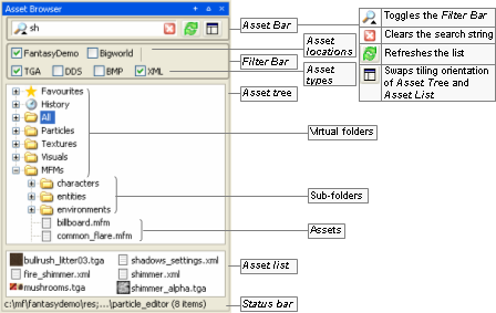
Asset Browser panel
Drag-and-drop operation is specific to the tool that implements it, and the type of asset being dragged, as described in the table below (asset types are listed in the order in which they appear in the Asset Tree):
| Asset type | Drop locationA | Effect |
|---|---|---|
| Particle | Viewport | Opens the dragged particle system for editing. |
| Texture | Renderer Properties sub-panel's Texture File drop-down listB. (only if Renderer is set to Sprite, Amp, Trail or Blur) | Sets the texture file to be used for current particle's sub-system. |
| Visual | Renderer Properties sub-panel's Visual File drop-down listB. (only if Renderer is set to Visual) | Sets the visual file to be used for current particle's sub-system. |
| MFM | Renderer Properties sub-panel's MFM File drop-down listB. (available for mesh-based particles) | Sets the MFM file to be used to override the mesh's material settings specified in its visual file. |
A — If the asset file is dropped in the Favourites special virtual folder, then it is added to that folder. For details, see Asset file. |
B — For details on these fields, see Renderer Properties sub-panel. |
Drag-and-drop operation in Particle Editor's Asset Browser panel
Defined in Asset Browser's configuration file (for details, see Customisation), virtual folders list files of a specific asset type.
For details on the listed asset types, see Assets.
The panel is divided in two parts:
General sub-panel
The upper sub-panel, which lists all particle systems in the current folder, with their sub-systems and their components.
Component sub-panel
The lower sub-panel, containing the configuration options of the sub-system's component selected in the Particle List of the General sub-panel.
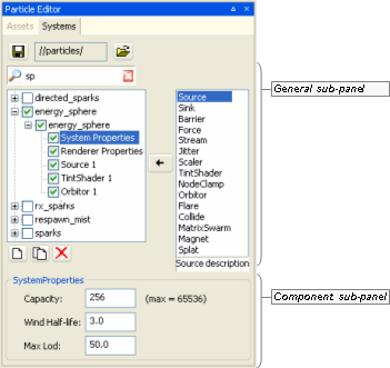
System panel
The panel contains the settings to be applied to the selected particle system.
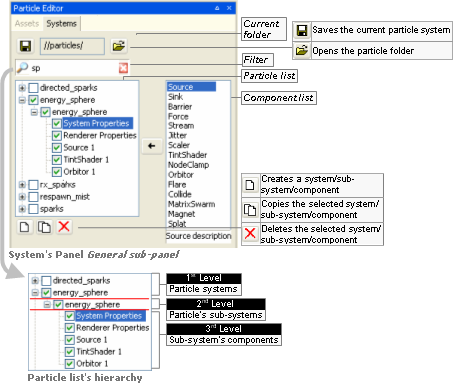
General sub-panel
The list below describes the fields on this sub-panel:
Saves changes to the current particle system.
Performs the same function as the File → Save Particle System menu item.A
Current folder
Folder which particle systems are displayed in Particle list.
The path is relative to the resource folder selected by the Open Folder —
— button.Opens the Open dialog box, where you can specify a new current folder.
The dialog box displays only the folders in the resources folders list (or
<res>). For details on how BigWorld compiles this list, see Starting the Tools.If this list is not set, then it will display the folders specified in the Path tag in bigworld/tools/particle_editor/paths.xml (for details on this file's grammar, see the document File Grammar Guide's section paths.xml).
Performs the same function as the File → Open Particle Directory menu item.A
Filter
Filter settings for particle system's name.
Please note that the filter applies only to particle-system's level.
For details, see Asset Browser panel.
Particle list
Hierarchical list with particle systems' information.
Particle systems
List of particles system files under the current folder (corresponds to the MetaParticleSystem object).
The selection/clearing of the check box propagates to all sub-systems.
Particle's sub-systems
List of particle sub-systems of the particle system (corresponds to the ParticleSystem object).
Individual sub-systems can be turned off by clearing its check box.
Pressing Ctrl while clicking the check box causes all other sub-systems to acquire the opposite value of the current sub-system.
Sub-system's components
List of components of the particle's sub-system.
As a minimum, every particle sub-system has the components System Properties and Renderer Properties.
Individual sub-systems can be turned off by clearing its check box, with the exception of System Properties and Renderer Properties.
Selecting a component causes its settings to be displayed in the Component sub-panel.
For more details, see the following sections:

Adds the component selected in Component List to the particle sub-system selected in Particle List.
Component list
List of particle components available to particle sub-systems.
Note that the System Properties and Renderer Properties components are not listed, since they are always created with new particle sub-systems by default, and cannot be deleted.

Creates a new particle system, sub-system, or component, depending on the type of item currently selected in Particle List.
If a particle system is selected:
Creates a new particle system, named system[n]B, containing sub-system named component, with components System Properties and Renderer Properties.
Add button — If a particle system is selected
If a sub-system is selected:
Creates a new sub-system, named component[n]B, with the components System Properties and Renderer Properties.
Add button — If a sub-system is selected
If a component is selected:
Creates a component of the type selected in Component List, named
<component_type>nB, and displays its respective configuration sub-panel.If a component involves 3D tools, then a gizmo will be displayed in the viewport.
Add button — If a component is selected

Copies the selected particle system, sub-system, or component.
If a particle system or sub-system is selected, then it will be named Copy of
<item_name>. If a sub-system's component is selected, then will be named<component_type>nB.
Deletes the selected particle system, sub-system, or component.
The user is prompted to confirm the operation only if a particle system or sub-system is selected.
The button will be disabled if the sub-system component selected is either System Properties or Renderer Properties.
A — For details, see Menu items.
B — Where n is a sequential number.
This is the lower part of the Systems panel, and displays the configuration options of the component selected in General sub-panel's Particle List.
This sub-panel allows the user to set the basic properties of the particle sub-system.
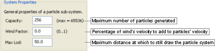
System Properties sub-panel
The list below describes the fields on this sub-panel:
Capacity
Maximum number of particles to be generated by the system.
Once this limit is reached, no more particles will be created, until some of them have been removed (via a Sink).
Value range is from 1 through 65536.
Wind factor
Amount of effect that the wind will have on the particle system's velocity.
Value ranges from 0.0 (wind velocity will not be added to particles' velocity, i.e., particles will not be affected by wind) to 1.0 (wind velocity will be fully added to particles' velocity).
Max LOD
Furthest distance from camera for which the particle system will still be drawn.
This sub-panel allows you to set the basic properties of the particle sub-system.
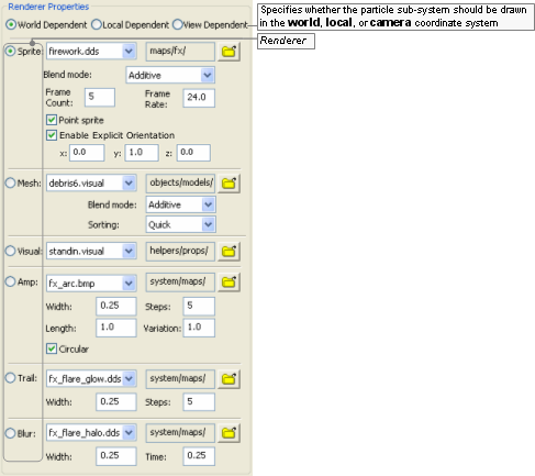
Renderer Properties sub-panel
This sub-panel contains various sections, one for each renderer:
Sprite section
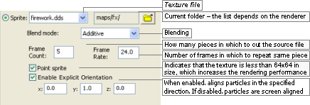
Sprite section
Mesh section
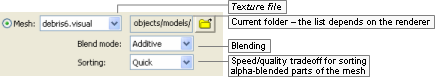
Mesh section
Visual section

Visual section
Amp section
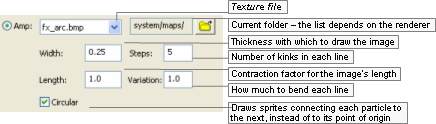
Amp section
Trail section
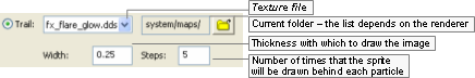
Trail section
Blur section
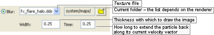
Blur section
The list below describes the fields on this panel:
World dependent
Sets whether the particle system should be drawn in the world's coordinate system.
Local dependent
Sets whether the particle system should be drawn in the camera's coordinate system.
If this check box is selected, then particles will move with the particle system that spawned them.
View dependent
Sets whether the particle system should be drawn in the camera's coordinate system.
If this check box is selected, then moving the camera will move the particles with it.
Useful for screen-based effects, e.g., if the player was to see stars after a concussion.
Renderer
The renderer to use on the particle sub-system.
Sprite
A sprite is a bitmap that rotates to face the camera perspective.
This renderer provides various blending modes, described in the Blending Mode lix box below.
Mesh
Allows the rendering of meshes exported from 3dMax or Maya using the Visual Exporter's Mesh Particles option button (for details, see 3ds Max visual exporter, and Exporting).
This allows blending mode and tint shaders to be used.
Visual
Allows a regular mesh to be drawn as a particle system.
It does not support tint shaders, unless they have a specially written shader, nor does it support blend modes like Mesh renderers.
Amp
Draws a series of sprites from the particle system's origin to each particle. Ideal for electrical effects.
Trail
Draws a trail behind each particle, while retaining information about previous positions of each one, allowing you to use centrifugal forces like Orbitor.
Blur
Draws a trail behind each particle, based on its velocity, but does not retain information about previous positions of each particle.
It works by drawing multiple particles along one vector, therefore it might not work as intended if you have centrifugal forces controlling the particles (in this case, use Trail instead).
Renderer fields
Texture file (available for Sprite, Mesh, Amp, Trail, and Blur)
List of files on the folder specified in the
button, and that are relevant to the
specified renderer.For the Mesh renderer, only visual files (.visual) will be listed. For all other renderers, these files will be listed: Bitmap images (.bmp), TrueVision Targa Graphic (.tga), and Microsoft Direct Surface (.dds).
Current folder (available for Sprite, Mesh, Amp, Trail, and Blur)
Opens the Open dialog box, where you can specify the folder from which to read the source files.
The dialog box displays only the folders in the resources folders list (or
<res>— for details on how BigWorld compiles this list, see Starting the Tools), and the ones listed in the configuration file bigworld/tools/particle_editor/paths.xml.Blend mode (available for Sprite)
List of available modes to blend the particle.
The options are described below:
Additive
Adds sprite's particle colour to the background using the alpha of the sprite's image as blend factor.
Additive alpha
Uses the inverse of the sprite's alpha as a mask on the background, and adds the sprite's colour.
Blended
Blends particles using the sprite's alpha channel.
Blended colour
Uses colour values to blend particles, instead of the alpha channel.
Blended inverse colour
The same as Blended colour. Available for backwards compatibility.
Solid
Renders particles as solid sprites, with no blend.
Shimmer
Shimmers the background, using the alpha channel to mask the shimmer.
Source alpha
Uses the sprite's alpha channel as a mask where alpha values less than 128 are transparent.
Frame count (available for Sprite)
Number of parts in which to cut the source file.
The Frame Count and Frame Rate fields provide a cheap way for using animated textures (the other method is using an animated texture — .texanim — file).
In this case, the source file should be a single bitmap with multiple frames in it. The Texture File on the right would have a Frame Count value of 3.

Example source file
Frame rate (available for Sprite)
Number of frames displayed per second.
For the example texture file above, a Frame Rate value of 0.5 would result in the lie cycle displayed below.
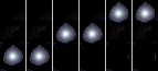
Example effect of Frame Rate value of 0.5
Point sprite (available for Sprite)
Indicates that the sprite is smaller than 64x64 pixels and has no animation, which reduces the amount of necessary memory, thus increasing the rendering performance.
Enable Explicit Orientation (available for Sprite)
When enabled, aligns particles in the specified direction. If disabled, particles are aligned to the screen.
Sorting (available for Mesh)
Determines the quality of the alpha-blending sorting and makes a trade-off between quality and speed.
The options are described in the list below:
None
The particle system as a whole will be rendered in order with respect to other sorted objects, and the triangles contained within will be sorted back to front. The particles themselves, however, will be rendered out of order.
Choose this method if speed is paramount and the visual artefacts introduced are not noticeable.
Quick
Sorting will be done in a way that allows the renderer to still draw in groups of 15.
This introduces some sorting inaccuracies, but maintains most of the speed of unsorted mesh particles.
This method is highly recommended if the sorting inaccuracies are not noticeable.
Accurate
Sorting of individual objects and triangles is performed.
This provides the most accurate sorting, but breaks the ability of the renderer to perform fast 15-at-a-time rendering, thus decreasing rendering performance.
If you choose this sorting method, then make sure to double-check the performance hit induced.
Width (available for Amp, Trail, and Blur)
Thickness in which to draw the image in the source file.
Texture length (available for Amp)
How compressed or elongated the original texture will be when rendering the particle — the particle is composed of continuous segments of the specified texture.
Fractional values below 1 specify the percentage by which the original image should be compressed, and values above 1 specify the percentage by which the image should be stretched.
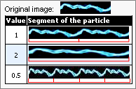
Example
Steps (available for Amp and Trail)
For Amp:
Number of kinks in each line.
For trail:
Number of times that the sprite will be drawn behind each particle, thus actually altering the length of the trail.
Variation (available for Amp)
How much to bend each line.
Circular (available for Amp)
Indicates that the sprites should be drawn connecting each particle to the next, instead of connecting each particle to the point of origin.
Time (available for Blur)
How long to extend the particle back along its current velocity vector.
This sub-panel allows the user to specify the dynamics of the particle sub-system, i.e., the particles' source position, how much they should spread, and the number of particles to be created, among other things.
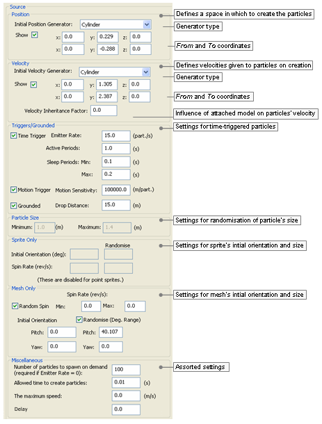
Source sub-panel
The list below describes the fields on this panel:
Position
Group of fields defining a space within which to create the particles.
Initial position generator
Geometry of the position generator.
The list below describes the available options, and how they affect the From and To fields:
Box (Enabled coordinates: From and To)
Cylinder (Enabled coordinates: From and To)
Line (Enabled coordinates: From and To)
Point (Enabled coordinates: From)
Sphere (Enabled coordinates: From)
Show
Toggles the visibility of the area defined for the position generator, and of the 3D gizmos attached to its initial and final (if applicable) points.
Note that changing the position of the 3D gizmos in the viewport automatically updates the appropriate From and To coordinates in the sub-panel.
From
The x, y, and z coordinates of the initial point of the position generator.
These values are automatically updated if you move the 3D gizmo in the viewport.
To
The x, y, and z coordinates of the final point of the position generator.
These values are automatically updated if you move the 3D gizmo in the viewport.
Only enabled if Initial Position Generator is set to Box, Cylinder, or Line.
Velocity
Defines a set of velocities that will be given to the particles on their creation.
Initial velocity generator
Geometry of the velocity generator.
The list below describes the available options, and how they affect From and To fields:
Box (Enabled coordinates: From and To)
Cylinder (Enabled coordinates: From and To)
Line (Enabled coordinates: From and To)
Point (Enabled coordinates: From)
Sphere (Enabled coordinates: From)
The gizmos define the possible velocity vectors — they are drawn from within the Initial Position Generator, and end within the Initial Velocity Generator.
The origin of the velocity vectors is determined by the type specified for it:
Box — Bottom corner of the box.
Cylinder — Centre of the base.
Line — Base point of the line.
Point — Point itself.
Sphere — Centre of the sphere.
Show
Toggles the visibility of the area defined for the velocity generator, and of the 3D gizmos attached to its initial and final (if applicable) points.
Note that changing the velocity of the 3D gizmos in the viewport automatically updates the appropriate From and To coordinates in the sub-panel.
From
The x, y, and z coordinates of the initial point of the velocity generator.
These values are automatically updated if you move the 3D gizmo in the viewport.
To
The x, y, and z coordinates of the final point of the velocity generator.
These values are automatically updated if you move the 3D gizmo in the viewport.
Only enabled if Initial Velocity Generator is set to Box, Cylinder, or Line.
Velocity inheritance factor
Amount of effect that the model to which the particle system is attached to will have on its final velocity.
Value ranges from 0.0 (the model's velocity will not be added to the particles' velocity, i.e., the particles will not be affected by the model's movement) to 1.0 (the model's velocity will be fully added to the particles' velocity).
Triggers/ Grounded
Group of fields for time-triggered particle sub-systems.
Time trigger
Indicates that the particle sub-systems will periodically generate particles.
All particle systems placed by World Editor must be time-triggered.
Emitter rate (particle/s)
Number of particles to be generated per second.
If the source seems to pause while releasing particles, then check the System Properties panel's Capacity field, and the setting for the Sink component.
Active period (s)
Period during which new particles will be generated.
After the Active Period, the particle system enters the Sleep Period.
Sleep period (s)
After an Active Period, a Sleep Period (i.e., a period of inactivity) might be specified — this type of particle behaviour is useful for bursts of activity.
If Min is set to zero, and Max is set to -1, then particles will be continuously generated.
If Max is set to -1, then only the Min value is used.
Min
Minimum period of inactivity (in seconds).
Max
Maximum period of inactivity (in seconds).
Motion trigger
Indicates that the particle sub-system is attached to a moving object.
Particles will be emitted per distance travelled by the sub-system.
Motion sensitivity (m/part)
How quickly the particles are released with motion, measured in metres per particle. This corresponds to the distance the system must move to release one particle.
To test this feature, change the selection in Sub-System Components list box to System Properties, then move the 3D gizmo.
Grounded
Indicates that particles should (if possible) be spawned at ground level.
Drop distance (m)
Maximum distance (in metres) allowed between the ground and particle's initial height (specified in Initial Position Generator's From's y field) if particle is to be generated.
In the example below, if Drop Distance is set to a value greater than 3.0, then no particles will be generated.
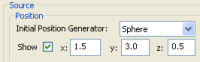
Example
Particle size
Defines the limits for randomising the size of the particles.
Minimum
Minimum size of particles.
Maximum
Maximum size of particles.
Sprite only
Group of fields defining initial orientation and spin rate for sprite-based particles.
Initial orientation (deg)
Inclination to apply to the particles (in degrees).
Spin rate (rev/s)
Number of revolutions per second to apply to the particles.
Randomise
If a value is not specified for Randomise, then all generated particles will contain the initial inclination/spin rate specified in this field. Otherwise, it will be randomised between the value in this field and the one in Randomise.
Initial orientation
Maximum value to be used for randomising the particles' inclination.
Spin rate
Maximum value to be used for randomising the particles' spin rate.
Mesh only
Group of fields defining initial orientation and spin rate for mesh-based particles.
Spin rate (rev/s)
Random spin
Indicates that the particles should revolve randomly, according to the settings below.
Min
Minimum value to be used for randomising the particles' spin rate.
Max
Maximum value to be used for randomising the particles' spin rate.
Randomise (deg range)
Indicates that the particles' pitch and/or yaw should be randomised according to Pitch and Yaw settings.
If a value is not specified for Randomise, then all generated particles will contain the pitch/yaw specified in this field. Otherwise, it will be randomised between the value in this field and the one in Randomise.
Pitch
Pitch of the initial position of the particles.
Yaw
Yaw of the initial position of the particles.
Pitch (Randomise)
Maximum value to be used for randomising the particles' pitch.
Yaw (Randomise)
Maximum value to be used for randomising the particles' yaw.
Miscellaneous
Number of particles to spawn on demand
Number of particles to create, for non-continuous emitters.
This field is mandatory for non-continuous emitters, which are designed to be dynamically created by the game (and not via World Editor). For these particle systems, a game event must force the creation of particles.
Time (in seconds) allowed for the creation of particles.
If the particles are not created within this time frame, then they will not be spawned. This is useful for grounded particles (see the Grounded check box), where system performance can be affected if too many particles are spawned.
The maximum speed
This is the maximum speed (in m/s) at which the particle system can be moving and still generate particles.
Delay
This is the delay in seconds that the action will wait before it starts.
This sub-panel allows the user to specify how long the particles should live.
Sinks are essential for most particle systems, because they remove unwanted particles and thus prevent the particle system from reaching its maximum capacity, at which point no more particles will be spawned.
Sinks can remove particles using the particle's age or its speed.
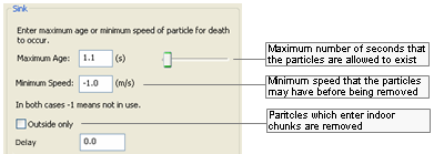
Sink sub-panel
The list below describes the fields on this panel:
Maximum age
Maximum lifetime (in seconds) of each particle.
A particle might be removed before its lifetime expires, if it reaches Minimum Speed.
Minimum speed
Minimum speed (in metres per second) that the particles may have before being removed.
A particle might be removed without reaching Minimum Speed if its lifetime expires.
Outside only
This ensures that the particles can only exist in outside chunks.
If a particle moves into and indoor chunk it is removed.
Delay
This is the delay in seconds that the action will wait before it starts.
This sub-panel allows the user to specify a barrier for the generated particles, and how they should interact with it.
Barriers can be used to bounce particles, remove particles (acts like a sink), or allow particles. To make particles bounce off the terrain, use a Collide sub-system instead of a Barrier. For more details, see Collide sub-panel .
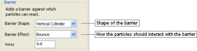
Barrier sub-panel
The list below describes the components of the Barrier sub-panel:
Barrier shape
Shape of the barrier.
Contains the following options:
None
Vertical cylinder
Box
Sphere
Barrier effect
How the particles should interact with the barrier.
Contains the following options:
Bounce
Remove
Allow
Wrap
Delay
This is the delay in seconds that the action will wait before it starts.
This sub-panel allows the user to specify a second force (independent of the initial force generator) to be applied to all particles in the sub-system.
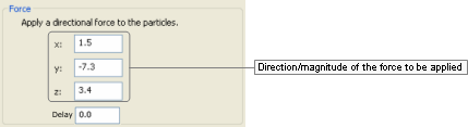
Force sub-panel
This component is different from the Stream component in which it does not have a half-life setting (for details, see Stream sub-panel).
The list below describes the fields in this panel:
x, y, z
Direction/magnitude of the force to be applied to the particles in the sub-system.
Delay
This is the delay in seconds that the action will wait before it starts.
This sub-panel allows you to specify how to apply a streaming effect to each particle.
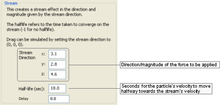
Stream sub-panel
This component is similar to the Force one, except in that it allows control of the amount of force imparted to each particle per time, via the Half-Life field (for details on the Force panel, see Force sub-panel).
The list below describes the fields in this panel:
Stream direction
Direction/magnitude of the force to be applied.
x, y, z
Coordinates for the direction/magnitude of the force to be applied to the particles.
Half-life (sec)
Number of seconds that the particle's velocity will take to move halfway towards the stream's velocity. A negative number means infinite half-life, i.e., the particles will not be affected by the stream.
Delay
This is the delay in seconds that the action will wait before it starts.
This sub-panel allows the user to add a jittering/wobbling effect to the generated particles.
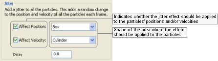
Jitter sub-panel
The list below describes the fields in this panel:
Affect position
Check box
Indicates that the jitter effect should be applied to the particles' positions.
Drop-down list box
Shape within which the effect positions are created. Larger objects result in larger differences in particle position, resulting in a stronger jitter effect.
The available options are:
Box
Cylinder
Line
Point
Sphere
Affect velocity
Check box
Indicates that the jitter effect should be applied to the particles' velocities.
Drop-down list box
Shape within which the velocity vectors are created. Larger objects result in larger effect vectors, resulting in a stronger jitter effect.
The available options are:
Box
Cylinder
Line
Point
Sphere
Delay
This is the delay in seconds that the action will wait before it starts.
This sub-panel allows the user to specify how to change the size of the particles over time.
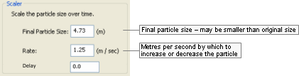
Scaler sub-panel
The list below describes the fields in this panel:
Final particle size
Final size of the particle (in metres). Might be smaller than particle's original size.
Rate
Number of metres per second by which to increase or decrease the particle.
Delay
This is the delay in seconds that the action will wait before it starts.
This sub-panel allows the user to specify how to colour the particles over time.
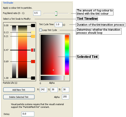
Tint Shader sub-panel
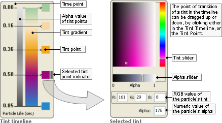
Tint Timeline and Selected Tint
The list below describes the fields on this panel:
Tint Timeline
Time point
Point of transition between two tints of the particle.
Alpha value
Displays the alpha value — in grey gradient — of each Tint Point in the timescale, and the values in between.
Bright areas indicate low value for alpha (low opacity), while dark areas indicate high value for alpha (high opacity).
Tint gradient
Displays the tint on each Tint Point, and the values in between.
Tint point
Tint selected for the particle at the specified point in the timescale.
Can be dragged up and down (except the first and last one), with value in the timescale being automatically updated.
Selected tint indicator
Indicates which Tint Point is currently selected.
The Selected Tint group of fields is automatically updated to reflect the selected tint values.
Fog blend ratio
This is the ratio of fog colour to blend with the tint colour.
Tint cycle time
Duration for the tint transition process.
The Time Point values in the Tint Timeline group are automatically updated.
Loop tint cycle
Indicates that the tint transition process should be continuously applied to the particle sub-system.
Selected tint
Tint slider/ selector
Composed of 2 parts:
Slider
Colour to be applied to the particle in the selected Time Point.
Selector
Luminosity of the colour selected in the slider part of this field.
The tint might also be specified in the RGB Value fields. The Tint Gradient and Tint Point in the Tint Timeline, and the RGB Values are automatically updated with the values selected.
Alpha sliderA
Opacity of the particle in the selected Time Point, in values between 0 and 1.
The brightest area of the slider indicates the lowest value for alpha (lowest opacity), while the darkest area indicates the highest value for alpha (highest opacity).
The Alpha Value in the Tint Timeline and the Alpha field are automatically updated with the value selected.
RGB values
R, G, B
Red, green, and blue components of the tint in the selected Time Point.
The tint might also be specified in the Tint Slider/Selector.
The Tint Gradient and Tint Point in the Tint Timeline, and the Tint Slider/Selector are automatically updated with the values specified.
AlphaA
Numeric value for the alpha to be applied to the particle in the selected Time Point.
Small values indicate low opacity, while great values indicate high opacity.
The Alpha Value in the Tint Timeline, and Alpha Slider are automatically updated with the value selected.
Add new tint
Adds a new Time Point in the Tint Timeline.
The new Time Point is added on top of the final one, so it is not immediately visible to the user. You have to drag it up in the Tint Timeline before specifying its settings.
Delete selected tint
Deletes the Time Point currently selected in the Tint Timeline.
The first and last Time Points cannot be deleted.
Delay
This is the delay in seconds that the action will wait before it starts.
A — While the Alpha slider varies from 0 to 1, the Alpha field varies from 0 to 255.
This component is used to determine that the generated particles should be clamped to the origin of the particle sub-system.
There are no settings for this component, just the delay in seconds that the action will wait before it starts.
This sub-panel allows the user to specify a point around which the particles should orbit along the y-axis.
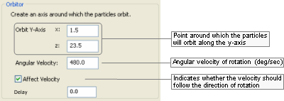
Orbitor sub-panel
The list below describes the fields on this panel:
Orbit y-axis
x,z
Coordinates of the point around which the particles will orbit along the y-axis.
To have the particle orbit around a different axis while placed in the word, simply rotate the particle sub-system in World Editor.
Angular velocity
Angular velocity of the orbit (in degrees per second).
Affect velocity
Indicates that the velocity should also be rotated with the particle.
If this field if not selected, then the velocity will always be in the same direction.
Delay
This is the delay in seconds that the action will wait before it starts.
This sub-panel allows the user to specify that a certain number of the particles should be spawned with a flare effect.
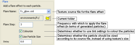
Flare sub-panel
The list below describes the fields in this panel:
Flare name
Texture used to apply the flare effect to the particles.
Folder
Opens the Open dialog box, where you can specify the folder from which to read the source files.
Flare step
Frequency in which to apply the flare effect to the particles. Every nth particle will have the flare effect.
Colourise
Determines whether to use the settings specified for the Tint Shader component (if any) to colour the particles (for details, see Tint Shader sub-panel).
Use particle size
Determines whether the particle should be sized as per its source file, instead of using the size of the chosen texture for the flare.
Delay
This is the delay in seconds that the action will wait before it starts.
This sub-panel allows the user to specify how much the particles should bounce when hitting the ground or other objects.
Unlike the Splat component, which determines that the particles should be removed immediately after hitting the ground or collidable objects, the particles with the Collide component are bounced according to the specified Elasticity. For details on the Splat component, see Splat sub-panel.
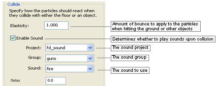
Collide sub-panel
The list below describes the fields in this panel:
Elasticity
Amount of bounce to apply to the particle when hitting the ground or other objects (in which case their BSP trees are used for the calculation).
The elasticity is applied as a factor to which the incoming velocity should be multiplied to determine the outgoing velocity.
For example, if Elasticity is set to 0.75 and a particle hits the ground at a downward velocity of 1.0 m/s, then it will bounce upwards at a velocity of 0.75 m/s.
Enable sound
Enable Sound
Determines whether a sound should be played when particles hit the ground or other objects.
Sound Project
The name of the sound project file from which to get the sound from. This is the project name is specified from the File
<engine_config>.xml.Sound Group
This is of the sound group to select the sound from.
Sound Name
The actual sound event to play when collision occurs.
Delay
This is the delay in seconds that the action will wait before it starts.
The MatrixSwarm effect allows particles to be attached to a node or a list of nodes. This involves writing Python scripts in the game, in order to attach this sub-system correctly.
Adding a MatrixSwarm in Particle Editor exposes the functionality in the game script.
There are no settings for this component, just the delay in seconds that the action will wait before it starts.
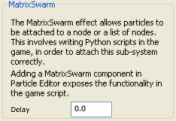
MatrixSwarm sub-panel
This sub-panel allows the user to specify a magnet effect to the particle's point of origin.
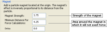
Magnet sub-panel
The list below describes the fields in this panel:
Magnet strength
Strength of the magnet.
Determines how strongly the particles are attracted to it, and how fast they move in its direction.
Minimum distance for force calculations
Area around the magnet in which it will not exert force.
Delay
This is the delay in seconds that the action will wait before it starts.
The Splat component is used to specify that the particles should disappear once they hit the ground or other objects.
Unlike the Collide component, which determines that the particles should bounce after hitting the ground or collidable objects, the particles with the Splat component are removed immediately after the collision (for details on the Collide component, see Collide sub-panel).
There are no settings for this component, just the delay in seconds that the action will wait before it starts.
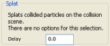
Splat sub-panel
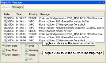
As mentioned in the beginning of this chapter, a particle system's XML file can be loaded by C++ coding, or Python scripting. The following sub-sections illustrate how to load the particle system with each mechanism.
The example below illustrates how to load the bonfire particle system via C++:
// FOR A META PARTICLE SYSTEM
MetaParticleSystemPtr system = new MetaParticleSystem();
system->load( "bonfire.xml", "particles/");

// to place the particle system somewhere other then the origin, attach it
PyMetaParticleSystem* pySystem = new PyMetaParticleSystem( system );
pySystem->attach( myMatrixLiaisonPtr );

// FOR AN INDIVIDUAL PARTICLE SYSTEM
// ParticleSystem::load will only load the first system in the file
ParticleSystemPtr system = new ParticleSystem();
system->load( "bonfire.xml", "particles/");

// can attach as shown above or explicitly set the position (not usu. Required)
Vector3 newPosition(1.f, 1.f, 1.f);
system->explicitPosition(newPosition);
Example of placing a particle system via C++
To understand the Particle Editor interface, it is useful to first describe how a BigWorld particle system works.
A BigWorld particle system consists of the following classes:
MetaParticleSystem
ParticleSystem
ParticleSystemAction
ParticleSystemRenderer
Along with their python wrappers:
PyMetaParticleSystem
PyParticleSystem
PyParticleSystemAction
PyParticleSystemRenderer
All classes can be found in the Particle project.
The following sub-sections describe each of these classes.
This is a container for a number of ParticleSystem instances, and is generally only used for static particle systems that are to be placed in World Editor.
This allows an artist to create a particle effect using a group of individual particle systems. For example, a fire could consist of flame, smoke and spark particle systems. Those could then be grouped into a fire MetaParticleSystem, which would appear as one object to World Editor.
A world builder can easily place such objects without concerns about each component.
This class contains the high-level information about the particle system, such as:
How many particles the system can contain.
Where the system is located.
How the system will be rendered — all particles in a ParticleSystem are rendered through a common ParticleSystemRenderer.
List of actions that determine how the particles behave.
This is a base class implementing a variety of actions on particles, which affect each one over its entire lifetime.
The most useful actions are described in the list below:
BarrierPSA
An invisible, impenetrable barrier in the shape of a box, sphere, or vertical cylinder.
At the barrier, particles can rebound, or be removed.
CollidePSA
Allows particles to collide with the collision scene.
If particles are mesh-based, then a rotation will be applied on collision — the rotation property is contained in the colour_ member.
FlarePSA
Draws a lens flare at the nth particle created (flare step).
ForcePSA
Applies a force to all particles in a particular direction.
JitterPSA
Adds random position or velocity to the particles.
MagnetPSA
Accelerates particles towards or away from a point.
OrbitorPSA
Causes particles to orbit around a vertical line.
ScalerPSA
Gradually grows or shrinks particles to a particular size.
SinkPSA
Destroys particles of a particular age or minimum velocity.
SourcePSA
Creates particles of a particular size, at a particular rate, within a given volume.
The rates can be time-triggered, motion-triggered, or neither, in which case the particles are created on demand by the application.
Only time-triggered particles can be previewed by the interface.
StreamPSA
Converges particles to a given velocity over time (half-life concept for the magnitude of the effect).
TintShaderPSA
Changes the tint of a particle over time (for sprites only).
This class provides various ways of rendering particles, as described in the list
Amp
Draws a series of sprites from the particle system's origin to each particle.
Ideal for electrical effects.
Blur
Draws a trail behind each particle, based on its velocity, but does not retain information about previous positions of each particle.
It works by drawing multiple particles along one vector, therefore it might not work as intended if you have centrifugal forces controlling the particles (use Trail instead).
Mesh
Uses a mesh (.visual file) exported from 3dMax or Maya using the Visual Exporter's Mesh Particles option button (for details, see 3ds Max visual exporter and Exporting.)
This has blending modes and allows tints to be applied to mesh particle systems.
PointSprite
A point sprite is a special case of Sprite renderer, in that it does not support textures bigger than 64x64 pixels or that have animation.
This restriction is made in order to decrease the amount of memory required, thus increasing rendering performance.
Sprite
A sprite is a bitmap that rotates to face the camera perspective. This renderer provides various blending modes.
Trail
Draws a trail behind each particle, while retaining information about previous positions of each particle, allowing you to use centrifugal forces like Orbitor.
Visual
Uses an arbitrary mesh (.visual file) as a particle.
This does not allow blending modes or tint shading without specialised shaders
For more details on the settings for each rendering mode, see Renderer Properties sub-panel.
Table of Contents
The BigWorld tools have consoles that provide information and allow tweaking to world builders, artists, and script writers.
These consoles are described in the following sections:
Available in World Editor, Model Editor, and Particle Editor, this console can be accessed via the Ctrl+F5 keyboard shortcut, and left by pressing Esc.
The console displays real-time frame rendering statistics, and gives you the ability to display graphs for the chosen items (see the bottom part of the viewport in the screenshot below).
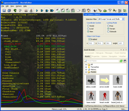
Realtime Profiling console
The list below describe the keyboard shortcuts available for the Realtime Profiling console:
Edit keys
Enter
Expands or collapses the profiling element currently selected — elements with children are indicated by an ellipsis (…) next to it.
Esc
Exits the console.
Home
Scrolls the list to display the first page.
Page Down
Moves the selection to the next profiling element in the list.
Performs the same function as the ] (square right bracket) keyboard shortcut.
Page Up
Moves the selection to the previous profiling element in the list.
Same as the [ (square left bracket) keyboard shortcut.
Symbols
Numpad + (Plus sign)
Scrolls the screen one line down.
Numpad - (Minus sign)
Scrolls the screen one line up.
[ (Left square bracket)
Moves the selection to the previous profiling element in the list.
Performs the same function as the Page Up keyboard shortcut.
] (Right square bracket)
Moves the selection to the next profiling element in the list.
Performs the same function as the Page Down keyboard shortcut.
Alphabetic keys
G
Draws a graph for the profiling element currently selected.
More than one element can be graphed at any one time. Each one will be assigned a different colour, which will be used to display the element's name, and to draw the graph itself.
Available in World Editor, Model Editor, and Particle Editor, this console can be accessed via the Ctrl+F7 keyboard shortcut, and left by pressing Esc.
The console gives access to the client watchers, and lets you change their values, to dynamically assess their effect in the world.
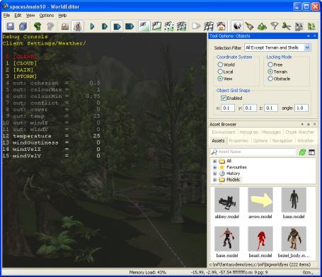
Debug (Watcher) console
The list below describes the keyboard shortcuts available for the Debug (Watcher) console:
Key modifiers
Alt
If [0-9] key in the alphanumeric keypad is pressed:
Selects item 40+[0-9], or 50+[0-9] (if Shift is pressed).
Ctrl
If [0-9] key in the alphanumeric keypad is pressed:
Selects item 20+[0-9], or 30+[0-9] (if Shift is pressed).
Shift
If [0-9] key in the alphanumeric keypad is pressed:
Selects item 10+[0-9], 30+[0-9] (if Ctrl is pressed), or 50+[0-9] (if Alt is pressed).
Edit keys
Backspace
Returns the list to the previous branch of the watcher tree.
Enter
If the selected node is not a leaf:
Navigates one level down in the watcher tree.
If the selected node is a leaf:
Opens the selected watcher for editing, or accepts the typed value if it is already in Edit mode.
Esc
If the watcher is in Edit mode:
Leaves Edit mode.
If the watcher is not in Edit mode:
Exits the console.
Home
Returns the list to the root of the watcher tree.
Page Down
If the watcher is not in Edit mode:
Moves the selection to the next item in the list.
If the watcher is in Edit mode:
Decreases the watcher's value by 1, 10 (if Shift is pressed), 100 (if Ctrl is pressed), or 1,000 (if Alt is pressed).
Page Up
If the watcher is not in Edit mode:
Moves the selection to the previous item in the list.
If the watcher is in Edit mode:
Increases the watcher's value by 1, 10 (if Shift is pressed), 100 (if Ctrl is pressed), or 1,000 (if Alt is pressed).
Symbols
Numpad + (Plus sign)
Scrolls the watcher list down.
Numpad - (Plus sign)
Scrolls the watcher list up.
Numeric keys
[0-5]
If the alphanumeric keypad was used:
Depending on the key modifier pressed (if any), selects the following:
n10+
n(if Shift is pressed)20+
n(if Ctrl is pressed)30+
n(if Ctrl+Shift is pressed)40+
n(if Alt is pressed)50+
n(if Alt+Shift is pressed)
Key combinations
Alt+Page Down
Decreases the watcher's value by 1,000.
Alt+Page Up
Increases the watcher's value by 1,000.
Alt+[0-9]
If the alphanumeric keypad was used:
Selects list item 4[0-9].
Alt+Shift+[0-9]
If the alphanumeric keypad was used:
Selects list item 5[0-9].
Ctrl+Page Down
If the watcher is in edit mode:
Decreases the watcher's value by 100.
Ctrl+Page Up
If the watcher is in edit mode:
Increases the watcher's value by 100.
Ctrl+[0-9]
If the alphanumeric keypad was used:
Selects list item 2[0-9].
Ctrl+Shift+[0-9]
If the alphanumeric keypad was used:
Selects list item 3[0-9].
Shift+Enter
If the watcher is in Edit mode:
Displays watcher modification history.
Shift+Page Down
If the watcher is in Edit mode:
Decreases the watcher's value by 1.
Shift+Page Up
If the watcher is in Edit mode:
Increases the watcher's value by 1.
Available in World Editor, this console can be accessed via the F11 keyboard shortcut, and left by pressing Esc.
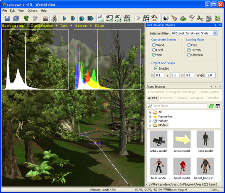
Histogram console
The list below describes the keyboard shortcuts available for the Histogram console:
Edit keys
Esc
Exits the console.
Numeric keys
0
If the alphanumeric keypad was used:
Toggles the graphing of luminance.
1
If the alphanumeric keypad was used:
Toggles the graphing of the red component in the RGB histogram.
2
If the alphanumeric keypad was used:
Toggles the graphing of the green component in the RGB histogram.
3
If the alphanumeric keypad was used:
Toggles the graphing of the blue component in the RGB histogram.
4
If the alphanumeric keypad was used:
Toggles the rendering of the scene background on the histograms.
5
If the alphanumeric keypad was used:
Decreases the vertical range ratio of the Luminance and RGB histograms.
6
If the alphanumeric keypad was used:
Increases the vertical range ratio of the Luminance and RGB histograms.
Available in World Editor, Model Editor, and Particle Editor, this console can be accessed via the Ctrl+P keyboard shortcut, and left by pressing Esc.
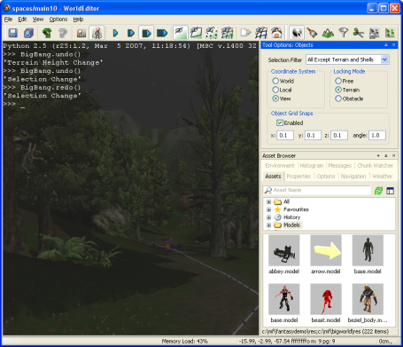
Python console
The list below lists the keyboard shortcuts available for the Python console:
Edit keys
Backspace
Deletes the character to the left of the insertion point.
Performs the same function as Ctrl+H.
Delete
Deletes the character to the right of the insertion point.
Performs the same function as Ctrl+D.
End
Moves the insertion point to the end of line.
Performs the same function as Ctrl+E.
Enter
If no command is specified:
Exits the console.
Esc
Exits the console.
Home
Moves insertion point to the beginning of line.
Performs the same function as Ctrl+A.
Key combinations
Ctrl+Backspace
Cuts to the clipboard all text between the insertion point and beginning of word.
Performs the same function as Ctrl+W.
Ctrl+Delete
Cuts to the clipboard all text between insertion point and end of word.
Performs the same function as Ctrl+R.
Ctrl+Insert
Pastes the content of the clipboard after the insertion point.
Performs the same function as Ctrl+Y.
Ctrl+Left Arrow
Moves the insertion point to the beginning of word.
Ctrl+Right Arrow
Moves the insertion point to the end of word.
Ctrl+A
Moves the insertion point to the beginning of line.
Performs the same function as Home.
Ctrl+D
Deletes the character to the right of the insertion point.
Performs the same function as Delete.
Ctrl+E
Moves the insertion point to the end of line.
Performs the same function as End.
Ctrl+H
Deletes the character to the left of the insertion point.
Performs the same function as Backspace.
Ctrl+K
Cuts to the clipboard all text between insertion point and end of line.
Ctrl+R
Cuts to the clipboard all text between the insertion point and end of word.
Performs the same function as Ctrl+Delete.
Ctrl+U
Cuts to the clipboard all text between the insertion point and beginning of line.
Ctrl+W
Cuts to the clipboard all text between the insertion point and beginning of word.
Performs the same function as Ctrl+Backspace.
Ctrl+Y
Pastes the content of the clipboard after the insertion point.
Performs the same function as Ctrl+Insert.
BigWorld tools (and the client as well) can be invoked from the command-line, as well as from icons or from Visual Studio.
Note
If the tools are installed from a version control system instead of the ZIP file, then the required Visual C++ DLL will not be present in the tools' executable folders and they will fail to open.
Whichever method you choose, the tool has to be able to locate the following folders:
The game's assets folder
BigWorld's assets folder
Note
When specifying paths, both forward slash (/) and backslash (\) characters can be used.
The client engine will try to determine the folders to be used in the following order:
{--res|-r}
game_res_folder[;bw_res_folder]argumentIf this argument is used in the command line, then the tool will use the folders specified in
game_res_folderandbw_res_folderarguments.bigworld/tools/
<tool>/paths.xml fileLocated on the same folder as the tool's executable, this file is the last resource for the client engine to determine the game's assets and BigWorld assets folders.
For details on this file's grammar, see the document File Grammar Guide's section paths.xml.
Table of Contents
The Asset Browser is a panel included in the BigWorld tools World Editor, Model Editor, and Particle Editor, that manages game assets in a uniform and effective way.
It can be customised via its configuration file ual_config.xml (for details, see Customisation) to attend to your particular needs.
The Asset Browser displays the various categories of assets available for each tool (e.g., models, shells, textures, etc...) in a tree structure, with the asset type being the topmost level, and the subsequent levels being composed of the folders containing assets of that type. It also allows you to search assets by their name — metacharacters can be used.
Similarly to web browsers, the tools also allow you to store your most-used assets (in the Favourites virtual folder), apart from automatically storing the most recently used assets (in the History virtual folder).
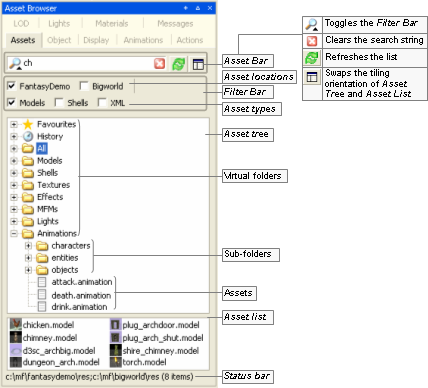
Asset Browser
The list below describes the fields on this panel:
Asset bar

Specifies the search string (with DOS-style wildcards) to dynamically apply to the Asset List.
The up/down arrow next to the magnifying glass expands/collapses the Filter Bar. A black arrow indicates that at least one filter criteria is checked in the Filter Bar, and a grey one indicates that none is checked.
 A
AClears the search string.
 A
ARefreshes the Asset List.
 A
ASwaps between horizontal and vertical tiling of the Asset Tree and the Asset List.
Filter bar
Asset locations
Restricts the location of assets to be displayed in the Asset List.
If no location is selected, then all folders in the resources folders list (or
<res>) will be searched.CIf at least one location is selected, then only those ones that are selected and are listed in the resources folders list will be searched. The list of locations is tool-specific, and can be configured.B
Asset types
Restricts the type of assets to be displayed in the Asset List.
The list of types is tool-specific, and can be configured.B
Asset tree
Set of virtual folders, in a tree-style view, giving access to the assets.
Virtual folders
Unless changed by the user, the list of virtual folders will always start with the nodes Favourites, History, and All. The remaining nodes are tool-specific, and can be configured either in the ual.config.xml configuration fileB, or via drag-and-dropD.
Virtual folders also have context menus. For details, see Virtual folder.
Asset list
List of assets resulting from the following combination:
Search string (specified in the Asset Bar).
Selected filters (specified in the Filter Bar).
Current virtual folder (specified in the Asset Tree).
Drag-and-drop from the list is supported, and is tool-specific. For details, see:
World Editor's implementation in Drag-and-drop
Model Editor's implementation in Drag-and-drop
Particle Editor's implementation in Drag-and-drop
Status bar
Displays information about the current item in the Asset Tree (virtual folder, or virtual folder's sub-folder), or in the Asset List (asset file).
For details, see Status bar information.
A — The appearance and inclusion of these buttons is tool-specific, and can be configured. For details, see Customisation.
B — For details, see Customisation.
C — For details on how BigWorld compiles this list, see Starting the Tools.
D — For details, see Drag-and-drop.
The status bar displays information about the item selected in the Asset Tree or in the Asset List, as described in the list below:
Virtual folder —
<result_folders>(<number_of_found_files>items)<result_folders>is the list of folders in the search path for which at least one asset was actually found.Example 7.1. Example
Assuming the following:
Search path contains the folders below:
C:\mf\gamebkp\res\avatars
C:\mf\gamebkp\res\npc
C:\mf\gamedev\res\avatars
C:\mf\gamedev\res\npc
Only the following folders contain at least one file with the extension configured for the selected virtual folder:
gamebkp/res/avatars (2 files with the relevant extension)
gamecli/res/avatars (2 files with relevant extension)
gamedev/res/npc (1 files with the relevant extension)
gametest/res/avatars (1 files with the relevant extension)
<result_folders>would then contain the following folders:gamebkp/res/avatars
gamedev/res/npc
The status bar would then display the following:
C:\mf\gamebkp\res\avatars;C:\mf\gamedev\res\npc (3 items)
The diagram below illustrates how this is established.
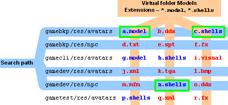
Sub-folder —
<source_folders>(<number_of_found_files>items)<source_folders> is the list of paths containing the folder which assets are displayed in the Asset List.
Note that all folders in the list will be displayed, regardless of them containing assets or not.
Example 7.2. Example
Assuming the following:
The search path contains the folders below:
C:\mf\gamedev\res\npc
C:\mf\gametst\res\npc
C:\mf\gamebkp\res\npc
The file system contains the folders below:
C:\mf\gamedev\res\npc
C:\mf\gamebkp\res\npc
The status bar would then display the following:
C:\mf\gamedev\res\npc;C:\mf\gamebkp\res\npc (
<n>items)
Asset file —
<absolute_path><filename>
Context menus are accessed by right-clicking a screen element.
The list below describes the menu items available in the virtual folder's context menu:
List view styles
List, Small icons, Big icons
Swaps the display style in the Asset List.
Change this panel's title
Opens the Change Asset Browser Panel Title dialog box, where you can specify new full window and short titles for the Asset Browser panel.
The Full Window Title is used as the panel's title, and the Short Title as the tab's title.
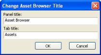
Change Asset Browser Title dialog box
Reload default folders
Reloads all virtual folders specified in the configuration file , in their original order.
Remove '
<name>'Removes the current virtual folder.
Clear contentsA
Clears the items in the list of the selected virtual folder.
A — Only available for Favourites and History virtual folders.
The list below describes the menu items available in the sub-folder's context menu:
List view styles
List, Small icons, Big icons
Swaps the display style in the Asset List.
Open folder in ExplorerA
Opens a new Windows Explorer window, displaying the contents of the selected sub-folder.
Copy path to clipboardA
Copies the sub-folder's absolute path to the clipboard.
A — If the sub-folder is available in more than one folder in the search path, then one menu item will be created for each of them.
The list below describes the menu items available in the asset list's context menu:
List view styles
List, Small icons, Big icons
Swaps the display style in Asset List.
The list below describes the menu items available in the asset's context menu:
List view styles
List, Small icons, Big icons
Swaps the display style in Asset List.
Add to favourites
Adds the selected model to the special virtual folder Favourites.
Open folder in ExplorerA
Opens a new Windows Explorer window, displaying the contents of the selected sub-folder.
Copy path to clipboardA
Copies the sub-folder's absolute path to the clipboard.
Edit in Model EditorC
Opens the selected item in Model Editor.
Edit in Particle EditorC
Opens the selected item in Particle Editor.
Open modelB
Opens the selected model in the viewport.
Add modelB
Performs the same functions as Model Editor's File → Add Model menu item. For details, see Menu items.
A — If the sub-folder is available in more than one folder in the search path, then one menu item will be created for each of them.
B — Available only in Model Editor.
C — Available only in World Editor
Items in the Asset Tree and Asset List provide drag-and-drop features, as described in the following sections.
The effect of virtual folder's drop action depends on where it occurs:
On Asset Tree
Virtual folder's position in the tree is changed to where it was dropped.
On Asset Tree of another Asset Browser panel
Virtual folder is copied to the other Asset Browser panel's Asset Tree.
Anywhere else
An Asset Browser panel is created, containing the Asset Bar, Filter Bar, Asset Tree (having only the dragged virtual folder), and Asset List. Note that the new panel allows drag-and-drop like any other panel (for details, see Drag-and-drop).
The effect of sub-folder's drop action depends on where it occurs:
On Asset Tree
A new virtual folder is created, with contents of the dragged sub-folder.
On Asset Tree of another Asset Browser panel
Sub-folder is copied to the other Asset Browser panel's Asset Tree.
Anywhere else
An Asset Browser panel is created, containing the Asset Bar, Filter Bar, Asset Tree (having only the dragged sub-folder), and Asset List. Note that the new panel allows drag-and-drop like any other panel (for details, see Drag-and-drop).
The effect of asset file's drop action depends on where it occurs:
On Asset Tree's Favourites virtual folder
File is copied to the virtual folder.
On application's viewport
Tool-specific behaviour.
For details, see:
World Editor's implementation in Drag-and-drop
Model Editor's implementation in Drag-and-drop
Particle Editor's implementation in Drag-and-drop
Anywhere else
Disabled.
Various elements of the Asset Browser can be customised, with each tool having its own configuration.
The configuration is saved on the tool's resources/ual folder, in the ual_config.xml file. For details on this file's grammar, see the document File Grammar Guide's section ual_config.xml.
The illustration below shows which elements can be configured, and how.
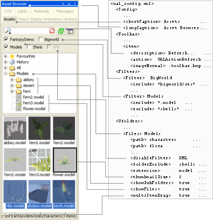
Example of Asset Browser customisation
The files displayed in the Asset List are determined by the list of search paths, the locations selected in Asset Locations, and the types selected in Asset Types.
Each node in the Asset Tree (with the exception of Favourites, History, and All) has a list of sub-folders to include in the search (specified in the configuration file (for details, see Customisation).
Each of these folders is then prefixed by all folders in the search path, which is specified according to the rule below:
If no check box is selected in Asset Locations:
The search path will contain all folders in the resources folders list (or
<res>) — for details on how BigWorld compiles this list, see Starting the Tools.If at least one location is selected
The search path will contain only the resource folders that are selected and are listed in the resources folders list.
Example 7.3. Example
Assuming the following:
The characters virtual folder is configured to search the following folders:
avatars
npc
The configuration file specifies the following Asset Locations:
Base assets — *base/res*
Level 1 (novice missions) — *level1/res*
Level 2 (expert missions) — *level2/res/*
Level 3 (final chapter) — *level3/res/*
Asset Locations has the following check boxes selected:
Base Assets
Level 1
Level 2
Resources folders list is set to:
C:\mf\level1\res;C:\mf\level2\res;C:\mf\level3\res
To determine
<search_path>:Make a list of all folders that are present in the resources folders list and are selected in Asset Locations:
In our example: C:\mf\level1\res;C:\mf\level2\res
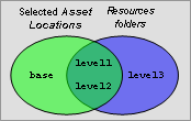
Use the list to prefix all search folders specified for selected virtual folder. The folder in the resulting
<search_path>will be:C:\mf\level1\res\avatarsC:\mf\level1\res\npcC:\mf\level2\res\avatarsC:\mf\level2\res\npc
Meta Data can be used to define arbitrary properties for existing objects. With meta data, you can add extra properties to models, particle systems or any objects in chunk. Those properties are listed along other properties and can be edited in the same way.
Currently we have two kinds of meta data:
Asset meta data: They are extra properties added to individual asset like model, particle system, etc. They are saved with the asset.
Instance meta data: They are extra properties added to the instance of an asset in the space. They are saved to chunk file by World Editor.
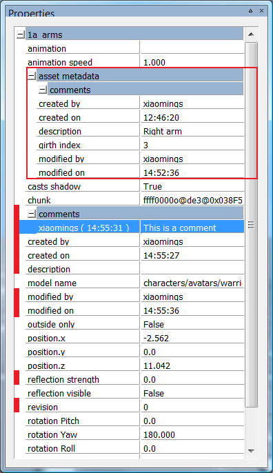
Meta Data
Above is the Properties panel of World Editor, it shows properties of a selected model. The properties listed under "asset metadata" (surrounded by the red rectangle) are the meta data properties of the model itself (asset meta data). The properties marked by a prefix red bar are the meta data properties of this chunk model instance (instance meta data).
Note: Asset meta data is read-only in World Editor.
Meta data properties are defined by XML files. Currently we only support three kind of meta data, they are:
Meta data for models: its definition file is defined in section editor/metaDataConfig/model of
resources.xml, the default value ishelpers/meta_data/model.xmlMeta data for particles: its definition file is defined in section editor/metaDataConfig/metaParticleSystem of
resources.xml, the default value ishelpers/meta_data/meta_particle_system.xmlMeta data for chunk items: its definition file is defined in section editor/metaDataConfig/chunkItem of
resources.xml, the default value ishelpers/meta_data/chunk_item.xml
Each section in the files defines a property. Its format is:
<PropertyName>
    <description> optional description </description>
    <type> TYPE </type>
</PropertyName>
Currently, the types we support are STRING, INT, FLOAT, COMMENT and DATETIME. If description section is not presented, we will use. For example, if you want to add a new property named "girth index", which is the index into a girth array to describe the model's girth. As "girth index" cannot be used as XML section name, a description must be provided. This property could be defined as follow:
<girth_index>
    <description> girth index </description>
    <type> INT </type>
</girth_index>
In addition to the properties defined in the XML files, each object with meta data also has some default properties. They are defined in the engine. Currently we only have 6 default properties: "created by", "created on", "modified by", "modified on", "comments" and "description".
"created by" and "created on" are automatically filled when the object linked to this meta data is first created, i.e. when a model is exported by the exporter, a meta particle system is created in Particle Editor or an object placed/cloned inside World Editor. "modified by" and "modified on" are automatically filled when there is any modification made to the object. All those fields are generated by the system and are read-only to the user.
"description" is a single string field used to add a simple description to the object while "comments" can have multiple entries under it. Besides the text, each comment also records the user who creates the comment and the time the comment is created.
If one of the definition files does not exist, the corresponding objects will still get their default properties.
Table of Contents
BigWorld tools such as World Editor, Model Editor and Particle Editor, give the user the ability to change the layout of the application's different panels using the Panel System.
The Panel System allows the user to have different parts of the application in different positions in the screen, as a tab or as a panel.
The picture below illustrates the basic elements of the system (fields are blurred to highlight the relevant items):
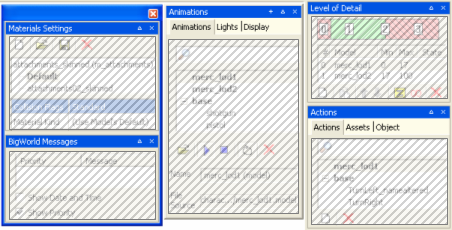
A window (left), a floating panel (middle), and two docked panels (right)
The panels can be manipulated in two ways:
via the title bar buttons
via drag-and-drop
The panels might be manipulated by the following buttons:
Create New Floating Panel button

Expand / collapse button
 /
/ 
Close button

Most of the manipulation can be done via drag-and-drop, with grey rectangles indicating the area where the dragged area will be fit.
Note
Pressing Ctrl makes the panel system ignore dockable areas.
To create a docked panel on an area of the viewport
Drag the desired tab or panel, and drop it near the top, bottom, left, or right of the viewport.
Before dragging the tab to the left side of the viewport
After dragging the tab to the left side of the viewport — New docked panel created
To create a new docked panel inside another docked panel
Drag the desired tab or panel, and drop it near the panel's title bar — if the drop happens inside the title bar, then a new tab is created.
Before dragging the tab near the panel's title bar
After dragging the tab near the panel's title bar — New docked panel created
To create a new floating panel
Drag the desired tab or panel, and drop it in the viewport.
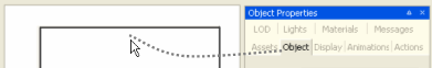
Before dragging the tab to the viewport
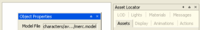
After dragging the tab to the viewport — New floating panel created
To create a new window
Drag the desired tab or panel, and drop it inside a floating panel, near its title bar — if the drop happens inside the title bar, then a new tab is created.
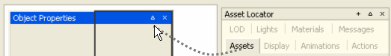
Before dragging the tab near the floating panel's title bar
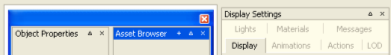
After dragging the tab near the floating panel's title bar — New window created
To create a new panel
Drag the desired tab or panel, and drop it near an existing tab or panel's title bar — if the drop happens near the title bar, then a new panel is created.
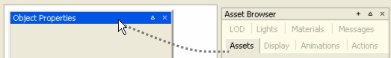
Before dragging the tab inside the panel's title bar
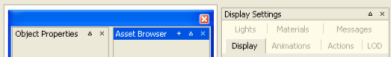
After dragging the tab inside the panel's title bar — New tab created
Upon exit, panel layouts are automatically saved to the layout.xml file inside the tool's application folder. Upon startup, the last panel layout is reloaded. If the layout file does not exist, then the tool will load its default panel layout. Please note that the layout.xml file should not be edited manually.
In all tools, the user has the option to load the tool's default panel layout, or reload the last customised layout.
For details on the menu items related to the Panel System, see:
World Editor's menu items in Menu items
Model Editor's menu items in Menu items
Particle Editor's menu items in Menu items
Table of Contents
The Offline Processor is one of the BigWorld tools used to generate a navmesh for each chunk in a space. It uses Recast to generate the meshes.
Note
The other tool provided by BigWorld to generate a navmesh is NavGen. For more details, see NavGen.
For details about Recast, refer to the project site, at http://code.google.com/p/recastnavigation/.
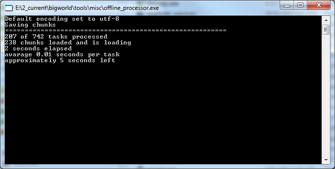
Offline Processor
The Offline Processor, located at
bigworld/tools/misc/offline_processor.exe, needs to be
configured so it knows where to find your game resources. This is done by
listing the resource paths, in order of precedence, in
bigworld/tools/misc/paths.xml.
In order for the Offline Processor to generate Recast navmeshes for
a space, that space must be properly configured, by setting the
navmeshGenerator option in
space.settings to recast. If this
option specifies any other generator, the Offline Processor will not
generate meshes. Modifying this value will not automatically cause chunks
to be dirtied, so if a navmesh already exists, the next generation will
have to be run in overwrite mode. For details refer to Running Offline Processor.
Recast uses settings that are stored in a Girths file, located at
bigworld/res/helpers/girths/xml by default. This file
contains profiles for entity types that will use each layer of the
navmesh. For details, see Server Programming Guide's
section Configuring Girth Information for Navmesh Generation.
The offline processor is designed to be run in a fully automated environment, and is therefore controlled via command line parameters.
offline_processor.exe [options]
The available options are:
-clusterIndexThe index of this machine within the cluster. See Cluster generation for more information.-clusterSizeThe size of the cluster in which this machine belongs. See Cluster generation for more information.-helpDisplays a usage message.-noguiIf no space is specified, or the space could not be found, this will avoid displaying the interactive GUI.-overwriteForces all data to be re-generated even if the chunks are not dirty.-spacePath to the space which is to be processed (e.g. "spaces/highlands").
For example, the following would force all data to be recalculated for the highlands space:
offline_processor -overwrite -space spaces/highlands
If no arguments are supplied, an interactive dialog will be displayed in order for a space to be chosen to process.
The offline processor allows you to accelerate the build process by spreading the workload amongst multiple machines (or multiple cores on a single machine). First, make sure that each computer has an up-to-date copy of the space being calculated. It is best to use cluster generation in conjunction with a version control system, such as CVS or SVN.
Use the clusterIndex and clusterSize
command line arguments. For example, if you have four machines to process
a single space you could use the following four command lines (one on each
machine),
offline_processor.exe -overwrite -clusterIndex 0 -clusterSize 4 -space spaces/highlands
offline_processor.exe -overwrite -clusterIndex 1 -clusterSize 4 -space spaces/highlands
offline_processor.exe -overwrite -clusterIndex 2 -clusterSize 4 -space spaces/highlands
offline_processor.exe -overwrite -clusterIndex 3 -clusterSize 4 -space spaces/highlands
The computers will proceed individually (there is no coordination between machines). To get the results from each computer back into one space use the version control system's check-in functionality (e.g., svn commit). There should be no overlap between the computers over the changed files, so merging individual files should be unnecessary.
Table of Contents
- 11.1. Configuring the space to use NavGen
- 11.2. NavPoly Generator menu items
- 11.3. NavPoly Generator status bar
- 11.4. NavPoly Generator keyboard shortcuts
- 11.5. NavPoly Renderer keyboard shortcuts
- 11.6. NavPoly Generator mouse controls
- 11.7. NavPoly Renderer mouse controls
- 11.8. Statistics dialog box
- 11.9. Cluster Generate dialog box
- 11.10. Navpoly Info dialog box
- 11.11. Navpolys, vertices and adjacency
- 11.12. Generating the navmesh on multiple machines
- 11.13. Generating the navmesh
- 11.14. Moving entities
- 11.15. Changing settings
- 11.16. Discontinuous navmesh
NavGen is one of the BigWorld tools used to create the navigation mesh. The navigation mesh is a space-covering connected set of polygonal prisms. It allows an entity to navigate between any two arbitrary points in the scene.
Note
The other tool provided by BigWorld to generate a navmesh is the Offline Processor, which uses Recast. For more details, see Offline Processor.
After you have created a space with World Editor, or changed a chunk, you can open NavGen and generate the navigation mesh.
NavGen uses the exclusive locks acquired in World Editor with the Lock Server (bwlockd). — for details, see Lock Server (BWLockD).
When you open NavGen, you are presented with two main windows and an error log:
NavPoly Renderer — Displays the 3D scene of the space.
NavPoly Generator — Displays the output from the navpoly generation.
Error Log — Outputs information messages and error messages.
The main windows both use the following colours to draw the chunk elements:
Blue — Navpoly
Red — Selected navpoly
Black — Empty space
Both windows are illustrated below:
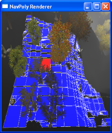
Navpoly Renderer
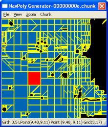
Navpoly Generator
A navpoly might be selected in either window, and is rendered in red in both of them
Double-clicking a navpoly on either window invokes the Navpoly Info dialog box, with height, and vertex coordinates and adjacency information on the selected navpoly. For more details, see Navpoly Info dialog box.
Each edge on a navpoly can be shared with the edge of an adjacent region. Alternatively, an edge may be marked as being adjacent to a different chunk. This means that movement between these two regions is allowed.
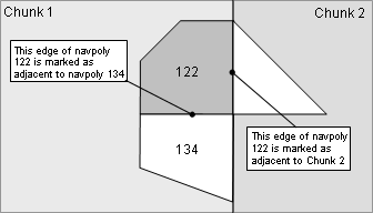
Navpoly edge demarcation
In order for NavGen to generate navmeshes for the chunks in a space,
the space must be properly configured. The
navmeshGenerator option in
space.settings must be set to
navgen. NavGen will also be used by default if the
navmeshGenerator option is not explicitly set.
Modifying this value will not automatically cause chunks to be dirtied, so
if a navmesh already exists, the next generation will have to be run in
overwrite mode. For details refer to Generating the navmesh.
If a space is opened that is not configured to use NavGen as its navmesh generator, NavGen will operate in read-only mode. It can still be used to inspect existing navmeshes for the space, but it will not be able to generate new meshes. For details, see the Inspecting the navmesh section.
The list below describes the menu items available in NavPoly Generator:
File → Open space
Used to open a space inside NavGen.
File → Open
Opens the Open dialog box, where you can select the adjacency map or chunk file that you want to load.
File → Remove all NavGen data
Removes the NavGen data for the current space.
File → Generate all
Generates the navigation mesh for all chunks in the space that have changed since the last generation.
File → Generate all overwrite
Generates the navigation mesh for all chunks in the space, regardless of whether it has changed since the last generation.
File → Cluster generate
Opens the Cluster Generate dialog box (for details, see Cluster Generate dialog box), which allows you to generate the navigation mesh in parallel (across multiple computers) for all chunks in the space that have changed since the last generation.
For details, see Generating the navmesh on multiple machines.
File → Exit
Quits the application.
View → Sets → All
Set all navmesh sets inside the current chunk to be visible.
View → Sets → None
Set all navmesh sets inside the current chunk to be invisible.
View → Sets → Individual Set Index
Toggle the visibility of individual navmesh set identified by the index.
View → Adjacencies
Toggles the visibility of grid point adjacencies as white lines overlaying the chunk.
These points are created during the flood fill phase of the generation of the navigation mesh — for details see Navpolys, vertices and adjacency.
Like BSP nodes, adjacencies will not be visible if the chunk was loaded from a chunk file; only when directly generated for a single chunk or loaded from a .tga file.
View → BSP nodes
Toggles the visibility of BSP nodes to a given depth of the BSP tree.
These nodes are created during the generation of the navigation mesh — for details see Generating the navmesh.
Like adjacencies, BSP nodes will not be visible if the chunk was loaded from a chunk file; only when directly generated for a single chunk or loaded from a .tga file.
The . (Period) and , (Comma) keys increase and decrease the depth displayed, respectively.
The BSP node is drawn as a polygonal prism with an additive colour. The list below describes how the BSP nodes will be displayed:
Blue
The node is completely traversable, i.e., it is a navpoly.
Green
The node is a combination of traversable and non-traversable regions.
Transparent
The node is completely non-traversable.
View → Polygon area
Toggles the visibility of the navpolys on both the Renderer and the Generator windows.
If selected, the navpolys in the chunk will be rendered in blue, and the selected one in red.
View → Polygon borders
Toggles the visibility of the borders of the navpolys on both the Renderer and the Generator windows.
View → Statistics
Opens the Statistics dialog box, with information about the chunk.
For more details, see Statistics dialog box.
View → NavPoly info
Opens the Navpoly Info dialog box, with information about the selected navpoly.
For more details, see Navpoly Info dialog box.
View → Rendered scene
Opens the NavPoly Renderer window (if it is closed) and brings it to the front.
View → Error log
Toggles the display of the Error Log dialog box.
Zoom → In on navmesh
Zooms in the chunk view in the NavPoly Generator window.
Zoom → Out on navmesh
Zooms out the chunk view in the NavPoly Generator window.
Chunk → DisplayA
Loads the navigation mesh for the chunk in which the camera currently is, and displays it.
Chunk → GenerateA
Generates the navigation mesh for the chunk in which the camera currently is, and displays it.
Chunk → Generate shrunkA
Performs the same operation as the Generate menu item (this item was implemented for previous versions, when multiple girths were not supported).
Chunk → ReannotateA
Reannotates the disconnected edges of the navigation mesh for the current chunk (annotation is the final step of navigation mesh generation).
Note
This functionality is now deprecated.
Help → Help
Opens the Help dialog box.
A — The shortcuts available for these menu items must be used in the NavPoly Renderer window. For details, see NavPoly Renderer keyboard shortcuts.
The status bar displays information about the current chunk. A typical status bar is illustrated below:

NavPoly Generator status bar
The list below describes the pieces of information displayed in the status bar, as they appear:
Mesh's girth label (in the example, Girth 0.5)
Girth label of the navigation mesh currently displayed, as configured in the file bigworld/res/helpers/girths.xml. For more details, see Changing settings.
Local chunk coordinates (in the example, Lpoint (2.61, 4.31))
Location of the mouse cursor in local chunk coordinates.
Global space coordinates (in the example, Point (-97.39, 4.31))
Location of the mouse cursor in global space coordinates.
Local navigation mesh coordinates (in the example, Grid (6,10))
Location of the mouse cursor in local navigation mesh coordinates.
In addition, when calculations are done (via Generate All, Generate All Overwrite, or Generate Cluster menu items — for more details, see NavPoly Generator menu items), the status bar displays the following information:
Number of chunk being processed (Text: Calculating chunk
n1ofn2)Number of chunks that have been calculated, and how many are to do in total.
During cluster generationA, the number of calculated chunks includes the number of chunks skipped by your computer (these chunks are calculated by other computers in the cluster).
Progress of calculation of current chunk (Text: Generation Status:
stage: Processedn1points (current stack sizen2))Rough estimate of how much calculation has been done in the current chunk.
There are usually about 40,000 points to process in a chunk.
A — For details, see Generating the navmesh on multiple machines.
The sections below list the keyboard shortcuts available for NavPoly Generator.
+ (Plus sign)
Zooms into the chunk view in the NavPoly Generator window.
Performs the same function as the Zoom → In menu item.A
- (Minus sign)
Zooms out of the chunk view in the NavPoly Generator window.
Performs the same function as Zoom → Out menu item.A
[ (Square left bracket)
Decreases the girth for which to display the navigation mesh.B
] (Square right bracket)
Increases the girth for which to display the navigation mesh.B
A — For more details, see NavPoly Generator menu items.
B — The available values for girth are defined in bigworld/res/helpers/girths.xml. For more details, see Changing settings.
The sections below list the keyboard shortcuts available for NavPoly Renderer.
Ctrl
Increases the navigation speed by a factor of 5. Can be used in conjunction with Caps Lock.
Caps Lock
Increases the navigation speed by a factor of 10. Can be used in conjunction with Ctrl.
Enter
Performs the same function as the Chunk → Display menu itemA.
A — For more details, see NavPoly Generator menu items.
! (Exclamation mark)
Generates the navigation mesh for the chunk in which the camera is, and displays it.
Performs the same function as the NavPoly Generator's Chunk → Generate menu itemA.
* (Asterisk)
Reannotates the disconnected edges of the navigation mesh for the current chunk.
Performs the same function as the NavPoly Generator's Chunk → Reannotate menu itemA.
, (Comma)
Increases the depth displayed of the BSP nodes.
To display BSP nodes, select the NavPoly Generator's View → BSP Nodes menu itemA.
. (Period)
Decreases the depth displayed of the BSP nodes.
To display BSP nodes, select the NavPoly Generator's View → BSP Nodes menu itemA.
@ (At sign)
Generates the navigation mesh for the chunk in which the camera is, and displays it.
Performs the same function as the NavPoly Generator's Chunk → Generate Shrunk menu itemA.
[ (Left square bracket)
Decreases the girth for which to display the navigation mesh.B
] (Right square bracket)
Increases the girth for which to display the navigation mesh.B
A — For details, see NavPoly Generator menu items.
B — The available values for girth are defined in bigworld/res/helpers/girths.xml. For details, see Changing settings.
The list below describes the mouse controls available for NavPoly Generator.
Left button click
Selects the navpoly.
Left button double-click
Opens the NavPoly Info dialog box for the selected navpoly.
For more details, see Navpoly Info dialog box.
Right button drag
Moves the navigation mesh in the direction of the mouse movement.
Scroll wheel rotate
Zooms the navigation mesh in and out, according to the direction of scroll.
The list below describes the mouse controls available for NavPoly Renderer.
Left button click
Selects the navpoly.
Left button double-click
Opens the NavPoly Info dialog box for the selected navpoly.
For more details, see Navpoly Info dialog box.
Right button drag
Rotates the camera in the direction of the drag.
This dialog box is accessed via the View → Statistics menu item (for details, see NavPoly Generator menu items), and displays statistics regarding the current chunk.
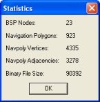
Statistics dialog box
The list below describes the information displayed in the dialog box:
BSP nodes
Number of BSP nodes in the navigation mesh.
These nodes are created during the generation of the navigation mesh — for more details see Generating the navmesh.
Navigation polygons
Number of navpolys in the navigation mesh.
Navpoly vertices
Sum of the number of vertices of all navpolys in the navigation mesh.
Most vertices will be counted more than once, since they might belong to more than one navpoly. This way, the number displayed for this field is the number of <vertex> tags present in the generated .chunk file for the chunk navigation mesh.
Navpoly adjacencies
Number of adjacencies of the vertices of all navpolys in the navigation mesh.
Note that adjacency is not generated for a vertex bordering an empty space.
Binary file size
Size of the navigation mesh in the .cdata binary file.
This dialog box is accessed via the File → Cluster Generate menu item, and displays options to run NavGen on the space across multiple machines (for details, see Generating the navmesh on multiple machines).
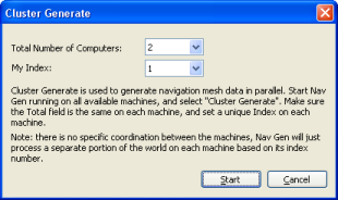
Cluster Generate dialog box
The list below describes the information displayed in the dialog box:
Total number of computers
Number of computers processing space data in parallel.
This number should be the same in all computers.
My index
Unique identifier for the computer processing space data.
This number should be unique.
This dialog box is accessed via the View → Navpoly Info menu item, or by double-clicking a navpoly on either window, and displays height and vertex coordinate and adjacency information for the selected navpoly.
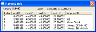
Navpoly Info dialog box
The list below describes the information displayed in the dialog box:
Navpoly ID
Integer pairs used to identify the navmesh. The first integer is its set index. The second integer is a unique identifier for the navpoly in the chunk.
Height
Vertical range of the navpoly prism.
Vertex table
Index
Vertex sequential number
Local x, Local z
XY coordinates of the vertex in local coordinates.
World x, World z
XY coordinates of the vertex in world coordinates.
Adjacent ID
ID of the element adjacent to the vertex.
The list below displays how the possible elements adjacent to the vertex are displayed:
Other navpoly in same chunk
Displayed as: Navpoly ID
Empty area
Displayed as: Blank
Chunk
Displayed as: Literal 'Other Chunk'
Obstacle
Displayed as: Literal 'Ahead: [S|M|R|C][S|M|R|C] [S|M|R|C][S|M|R|C] [S|M|R|C][S|M|R|C]'
The text after the literal contains information about obstacles ahead, 45° to the left, and 45° to the right of the vertex.
It consists of three pairs of obstacle information: the first letter of the pair contains information about the bottom half of the corresponding direction, while the second letter contains information about the top half of the corresponding direction.
The list below describes the possible values of the pairs' letters and the corresponding obstacle status:
S — Solid
M — Mixed
R — Reserved
C — Clear
For example, an Adjacent ID column with value of 'Ahead: SM SC MM' stands for the following information about obstacles and the vertex:
Ahead
Bottom half — Solid
Top half — Mixed
45º to the left
Bottom half — Solid
Top half — Clear
45º to the right
Bottom half — Mixed
Top half — Mixed
A chunk is divided into navpolys, which are convex polygons. The polygon indicates an area where it is clear to move. Therefore, if a room is completely empty, it will have a single navpoly. However, if it has a bench in the middle, then it will have four navpolys, to avoid covering the bench —i.e., there will be a hole in the passable area of that chunk. Entities can move around a navpoly, and between adjacent ones.
The polygons have a height too, so they are actually polygonal prisms. The navigation mesh works in 3D for scene elements such as staircases and overhangs. Even though it can be used for flying entities, enhancements are needed for better support.
For NavGen, a vertex is a continuous portion of the navpoly border that is adjacent to only one other navpoly, chunk, object, or empty space. It means that if one side of a navpoly is adjacent to 2 others, then that side has 2 vertices.
In the illustration below, note the following:
Navpoly 2 has one side that is adjacent to navpolys 6 and 7. NavGen will generate one vertex for each navpoly adjacency.
NavGen might generate a vertex with no adjacency for vertices that are bordering an empty space. For the portion of the side of navpoly 3 that is adjacent to an empty space, NavGen will generate 1 vertex, but no adjacency.
NavGen generates vertex data for each navpoly at a time. That means that vertices shared between navpolys in the same chunk are present in the resulting .chunk files twice — once for each navpoly. This excludes vertices that are adjacent to another chunk.
The illustration below shows an example of a chunk with 11 navpolys and 2 empty spaces, and a table with the number of vertices and adjacencies for each of them.
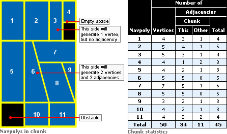
Navpolys In Chunk vs. Chunk Statistics
Running NavGen on large spaces can take some time to process. To reduce processing time, it is possible to divide the computation across multiple computers, each one working only on a subset of chunks (first make sure that each computer has an up-to-date copy of the space being calculated). It is best to use cluster generation in conjunction with a version control system, such as CVS or SVN.
Select the File → Cluster Generate menu item (for details, see NavPoly Generator menu items), then in the Cluster Generate dialog box (for details, see Cluster Generate dialog box), enter the number of computers that will be generating the cluster, and a unique index for each of them. The computers will proceed individually (there is no coordination between machines). To get the results from each computer back into one space use the version control system's check-in functionality (e.g., cvs commit). There should be no overlap between the computers over the changed files, so merging individual files should be unnecessary.
If you stop the process (because, for example, NavGen did not finish overnight and you wish to use the machines again), then you can continue the calculation process when convenient. In this case, NavGen will quickly skip over already calculated chunks.
Besides generating the navigation mesh for the whole space, it is also possible to generate it just for a specific chunk.
To do so, position the camera in the desired chunk, then select the Chunk → Generate menu item. This method of mesh generation does not display progress status.
When generating the navigation mesh for the space (via the File → Generate All or File → Generate All Overwrite menu item), the first chunk to be processed is the one where the camera is in. Upon completion of the chunk, the adjacent ones will be processed. Only chunks changed in World Editor since the last generation will be processed.
The generation process takes approximately 3 to 5 minutes per chunk, and if all chunks are being processed, then a real-time view of the progress is displayed in the window.
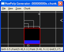
Progress of navigation mesh generation — Step 1
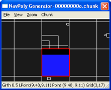
Progress of navigation mesh generation — Step 2
Once the navigation mesh has been generated, the results can be viewed on a chunk-by-chunk basis. In the NavPoly Renderer window, navigate to the desired chunk, then press Enter — this will display the navigation mesh for that chunk (for details, see NavPoly Renderer keyboard shortcuts).
For more details on the format of the generated .chunk files, see the document Server Overview's section Server Components → CellApp → Navigation System.
The process of generating the navigation mesh for a space is a time-consuming one, due to the amount of calculation necessary for a fast and efficient final product.
For completely flat chunks without obstacles, the generated mesh will be composed of a single large navpoly. But any other geometry requires an initial matrix of collision scene tests from each direction to every other one, followed by a BSP-based reduction scheme to arrive at the final navpolys. The time invested in creating an efficient mesh is greatly compensated by the result of a fast navigation through the space.
Please note that while this may seem slow, the time spent on adding scene elements to the world via World Editor will in most cases amount to much longer than the time taken to generate the navigation mesh for it. Furthermore, the navmesh generation can occur overnight
On the other hand, if you have written your own tools to auto-generate large parts of your world (and server-controlled entities can roam freely over those parts), then this equation could change. If that is your case, then contact the BigWorld support engineers so that they can guide you in auto-generating your world and the navigation mesh at the same time.
Based on terrain and other geometric information in the chunk files, NavGen creates the convex navpoly polygons in three main phases:
It flood fills each chunk, using client physics rules.
It uses a BSP algorithm to recursively subdivide the space and form convex polygonal prisms.
It then annotates the polygon edges and writes the results back into the binary .cdata files.
The following sub-sections describe this process in details.
The flood fill algorithm currently samples the chunk geometry using a grid of 0.5 metre resolution.
This is the default resolution, and whilst it is configurable via bigworld/tools/misc/navgen_settings.xml, it is ideal for human-sized entities, since a courser resolution would be less accurate, and a finer resolution would end up generating excessive navpolys. Also, since the same point in the grid may exist at several heights within each chunk (in case of elements such as tunnels and bridges), 16 grids are used to describe the connectedness of the scene in each chunk.
Within each grid, the movement is tested from each point on the grid to its eight neighbours. As an intermediate step, this information is saved to a TGA file (the file is saved in the folder specified by the option floodResultPath in bigworld/tools/misc/navgen_settings.xml). For more details, see Adjacency map filtering (blue).). NavGen also saves the origin point, the sample resolution, and the y-values for each grid point to the TGA header. This means that the polygons can be generated from the TGA file alone — the TGA file could be viewed with an ordinary TGA viewing program if only one grid was used.
The flood fill algorithm currently only allows bi-directional movements, i.e., movements allowed in only one direction — such as jumping off a cliff — are not accepted.
The algorithm also checks the hulls of neighbouring chunks. It stops flooding when it crosses to another hull (actually it stops flooding just after crossing). Thus, each chunk's grids slightly overlap another one by one flood movement unit, and as far as navpoly are concerned this is how chunk adjacencies are calculated. For more details, see Adjacency map filtering (blue).
The following points are the seed points for the flood fill:
Centre of the chunk.
Points along the perimeter of the chunk and its internal portals — they are moved in slightly towards the centre of the chunk along the portal plane normal.
Points where an entity has been placed in the scene.
Having multiple seed points is necessary in cases where a chunk is composed of multiple disjoint but internally connected regions.
After the calculation, each chunk will have a 3D bitmap representing an adjacency grid.
Smoothing filters are applied to this adjacency grid bitmap, to smooth it out and remove any artifacts that would lead to degenerate polygons.
In general, this step only removes connections — it does not add them. If the floodResultPath configuration option is defined in bigworld/tools/misc/ navgen_settings.xml, then TGA files are saved to that path. These files represent the states before and after filtering.
This step reduces the filtered adjacency grid bitmap into a set of convex polygonal prisms. The fewer resulting prisms the better, since less geometry will need to be loaded by the server during the game.
The basic approach is to sub-divide the space by generating a 3D BSP, until each leaf node is entirely traversable, (i.e., it presents no obstructions for navigating), or entirely non-traversable. It makes the process easier that all leaf nodes of a BSP are guaranteed to be convex (a nice side effect of this approach is that, given a point, the BSP could be used to quickly find its navpoly. Such feature is not currently implemented, because performance has not been an issue — and the BSP would take extra memory — but it is good to keep this ability in mind).
The heuristic for splitting the space has two goals:
Try to produce a balanced tree, by splitting the space near the centre.
Try to split the space along boundaries between traversable and non-traversable regions.
For each point in the region, if the point has an adjacency in one direction (e.g., north), but none along one of the neighbouring directions (e.g., northwest or northeast), then mark a possible split along the line from north to south. The split is given a value according to its distance from the centre of the region, and the split closest to the centre is chosen.
To make the tree more balanced initially, if the region is larger than the value of constant EVEN_SPLIT_THRESHOLD (defined in C++ source file src/lib/waypoint/ waypoint_generator.cpp, with a default value of 25 metres) in any dimension, then it is split in half along the shortest axis. In some cases, a vertical split must be made.
After having generated the BSP, the process of forming the polygons is simple, consisting of the following sub-steps:
Vertices are created wherever lines intersect.
The edge of a polygon will be split if it is adjacent to more than one polygon, since each vertex can have only a single adjacency.
If the resulting polygon is convex, then adjacent polygons are joined.
This sub-step is repeated until it is no longer possible to combine any polygons. Often, 50% of polygons can be joined.
Chunk adjacencies are calculated.
This sub-step calculates chunk adjacencies.
As mentioned in section Adjacency and height map calculation (from black to blue), chunks may overlap each other by one flood movement unit. This way, NavGen can use this information and determine that if both sides of an edge are inside the hull of a neighbouring chunk, then this edge is marked as adjacent to that chunk.
Note that the adjacency will be marked in the .cdata file as being related to a chunk, but not which one. This is because a space might be connected to another one in the server, in which case the adjacent chunk will not be assigned until runtime.
With help from the GPU, the edges of navpolys that are not adjacent to another one (i.e., adjacent to a non-traversable region) are annotated with the situation visible from that edge.
The scene looking out from that edge is rendered orthographically into an offscreen buffer and then analysed. The situation is represented with two bits for each of the top half and the bottom half of the screen.
The following list describes the possible values for these two bits:
Completely clear
The edge has visibility to the navpoly ahead of it, even though the navpolys are not adjacent.
Example: A chasm between the two navpolys.
Completely blocked
The edge has no visibility to other navpolys.
Example: A wall between the navpolys.
Partially blocked
The edge has visibility to some navpolys, but not to others.
Example: A tree between the navpolys, so some of them are visible through the branches.
This procedure is performed considering three directions for each edge (resulting in 12 bits of information per non-adjacent edge):
Straight ahead
45º to the left
45º to the right
The illustration below describes the assembling of the navpoly adjacent ID ABCDEF:
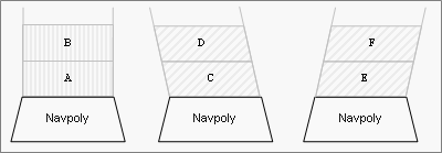
Assembling of navpoly adjacent ID field with value ABCDEF
The actual value stored in the .chunk file for the vertex's adjacent_ID field is the logical NOT of this 12-bit value, since BigWorld considers all negative adjacency values as meaning that none exists.
The purpose of annotation is to provide hints about the world to AI algorithms on the cell that go beyond simply what regions are traversable and which are not. At the moment, the method findCover is the only one that takes advantage of this situational information. Adding others, however, will be trivial if the need arises.
After generating the space's navmesh, you may want to examine the result. You can do this by doing the following:
In the NavPoly Generator window, select the View → Rendered Scene menu item (for details, see NavPoly Generator menu items) — this will move focus to the NavPoly Renderer window.
Inspect the navmesh
In the NavPoly Renderer window, navigate to the point of interest using either the keyboard or the mouse (for a compete list of keyboard shortcuts and mouse controls available in NavPoly Renderer, see NavPoly Renderer keyboard shortcuts and NavPoly Renderer mouse controls).
Display the navmesh by pressing Enter.
Navmeshes of different girths can be selected using the [ (left square bracket) and ] (right square bracket) keys.
The navmesh is displayed as a collection of blue polygons.
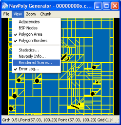
Generated navmesh — Navpoly Generator
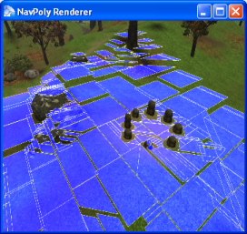
Generated navmesh — Navpoly Renderer
Once there is a navigation mesh for the space, you can use the Entity.navigate and Entity.navigateStep methods in cell scripts to move the entities. For more details, see the Client Python API's entry Main Page → Cell → BigWorld → Classes → Entity → navigate.
You should use the filter AvatarDropFilter on
the client for such entities. This is because the position sent by the
server is the top of the navpoly prism, which is dropped up to two
metres[2] to find the real position on the ground. This saves the
server from doing many ground position tests, and improves the client's
interpolation, so that interpolated positions can also look right. If you
do not use this filter, then the entities will hover slightly above
hills.
The settings for NavGen are stored in the bigworld/tools/misc/navgen_settings.xml file[3].
<navgen_settings.xml> <space> spaces/desert </space>
Example file bigworld/tools/misc/navgen_settings.xml
| Space to load. |
| World Editor Lock Server (bwlockd) control. For details, see Lock Server (BWLockD) |
| Determines if NavGen should connect to a bwlockd server. |
| Path where the pre-filter and post-filter TGA files are generated. For more details, see Adjacency map filtering (blue). |
NavGen also uses settings that are stored in a Girths file, located
at bigworld/res/helpers/girths/xml[4] by default. This file contains profiles for entity types
that will use each layer of the navmesh. For details, see Server Programming Guide's section Configuring Girth Information for Navmesh Generation.
The final space might contain areas that are not reachable on foot from other areas, examples might be the roofs of buildings, ledges, or pits.
Entities should be placed in islands of navigable terrain to ensure that their navigation mesh is generated. Also, be aware that unreachable areas that span multiple chunks will still have navmesh generated for them, even if there are no placed entities present.
[2] Navpolys cannot be taller than two metres
[3] For details on this file's grammar, see the document File Grammar Guide's section navgen_settings.xml.
[4] For details on this file's grammar, see the document File Grammar Guide's section girths.xml.
Table of Contents
BigWorld offers plug-ins that allow you to export geometry and animation data from 3ds Max and Maya to the formats used by the game engine.
BigWorld offers plug-ins for exporting visuals and animations, supporting 3ds Max versions 2008, 2009, 2010 and 2011.
The 3ds Max visual exporter is a plug-in that exports mesh data to the .visual format used by the BigWorld engine.
It exports meshes, physiqued meshes, skinned meshes, transform nodes, morph targets, BSP trees, hard points, and portals, and can also generate tangents and binormals for normal mapping.
In order to access the Visual Export plug-in, set the Select File To Export dialog box's Save As Type drop-down list box to Visual Exporter (*.VISUAL), as illustrated below:
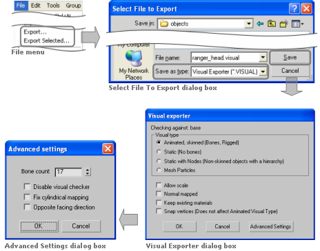
Accessing the Visual Export plug-in in 3ds Max
Note
For unskinned meshes Visual Exporter can automatically select a 32-bit index buffers if there are more than 65355 vertices in the model. However, skinned meshes are limited to 65355 vertices.
The client engine can load both 16- and 32-bit index buffers automatically, but some low-end graphic cards do not support the latter. On those cards, objects with 32-bit index buffer will not render.
The components of the Visual Exporter and Advanced Settings dialog boxes are described below:
Visual type
Type of visual being exported, and hence what kind of information to save.
Animated, skinned
Specifies that the plug-in should export everything as is, i.e., every piece should be exported as a separate object, and all transform nodes and morph targets should be exported.
This option should only be used for visuals that have moving parts rigged with physique, skinned, or separate moving parts.
This option does not generate BSP trees from the meshes. If you want to have a (static) BSP tree for an animated object, then you will have to create a custom one.
Static
Specifies that the plug-in should combine all meshes into one, discarding all transform nodes and modifiers, and generating a BSP tree for the combined mesh (unless there is a custom one in the current scene).
This option should be used for shells and other static objects placed in the scene.
Static with nodes
Specifies that the plug-in should combine all meshes into one, exporting all transform nodes.
This option is similar to Static, except that it will export all transform nodes for the scene.
Mesh particles
Specifies that the plug-in should allow these meshes to be sorted when rendered, so that alpha blending works correctly. Each individual object in the scene is exported as one particle, in the format used by the mesh particle renderer.
There is a limit of 17 particle meshes exported for each mesh particle object.
Visuals exported using this option can be used as a particle system in Particle Editor. For details, see Renderer Properties sub-panel.
Allow scale
Indicates that the transform nodes should be exported with scale.
This is generally not necessary, and should only be used if you want to export animations that include scale.
Normal mapped
Specifies that the plug-in should create additional data to be used for normal-mapping the model.
This option must be checked to use a normal-mapped material on the model.
Keep existing materials
Specifies that the plug-in should keep changes made to the material in Model Editor.
This option must be checked if you are overwriting a previously exported model, and want to keep material changes made in Model Editor.
Snap vertices
Specifies that the plug-in should snap the vertices of all geometry to the nearest tenth of a millimetre.
This option has been added primarily to support the new use of portals — because the grid and axis alignment restrictions have been removed for portals, snapping portals to the nearest tenth of a millimetre can pull portals off bounding box or hull boundaries.
This option does not affect geometry exported when the Visual Type drop-down list box is set to Animated.
Advanced Settings dialog
Bone count
Specifies the number of bones used by the Visual Splitter to divide up any mesh.
It is set to a default of 17 because all BigWorld skinned shaders are designed to use a maximum of 17 bones. When a visual file uses more than 17 bones, the Visual Splitter divides the object into 17, or less, bone segments.
Only change this field if you have created shaders that support a different number of bones.
The field's maximum value is 87, which is the upper limit of BigWorld vertex format.
Disable visual checker
Specifies that the plug-in should not check the exported model against the visual rules. A
Fix cylindrical mapping
Specifies that the plug-in should try to use an alternative method for generating texture space vectors used for normal mapping.
This option must be checked if there are artifacts along seams when using normal-mapped shaders.
Opposite facing direction
Specifies that the model has been modelled facing in the incorrect direction and that it should be rotated by 180 degrees so that is appears correctly inside the engine.
A — The rules are defined in bigworld/tools/exporter/resources/visual_rules.xml. For details, see Validation rules.
The plug-in automatically generates the file visualexporter.cfg, under 3ds Max's folder Local Settings/Application Data/Autodesk/3dsmax/MaxVersion/enu/plugcfg.
The list below describes the configuration options written to this file:
allowScale
Last value set for the Allow Scale check box in the exporter dialog box.
bumpMapped
Last value set for the Bumpmapped check box in the exporter dialog box.
exportMode
Last export mode used in the exporter dialog box.
unitScale
Conversion factor for units between 3ds Max and BigWorld.
The default value is 0.1, which means that 1 unit in 3ds Max equals 0.1 units in BigWorld.
It is important to note that you need to change this value in both animationexporter.cfg and visualexporter.cfg.
This configuration option can be set only in the configuration files.
The 3ds Max Animation Exporter is a plug-in that exports animations to the .animation format used by the BigWorld engine.
It supports exporting of node and morph animations (using the morpher modifier).
To access the Animation Export plug-in, in the Select File To Export dialog box set the Save As Type drop-down list box to Animation Exporter (*.ANIMATION), as illustrated below:
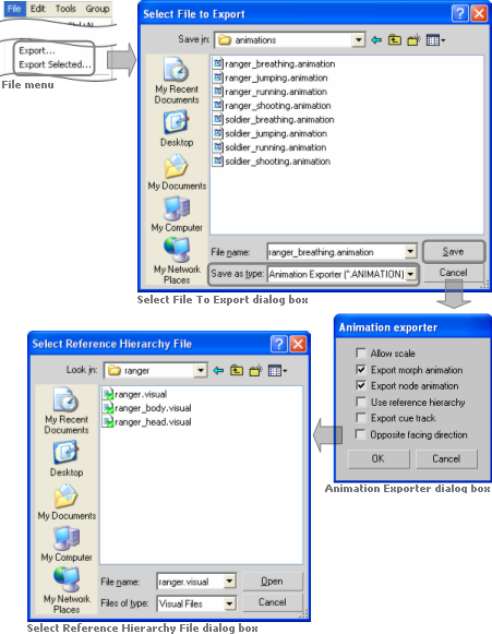
Accessing the Animation Export plug-in in 3ds Max
The list below describes the components of the Visual Exporter dialog box:
Allow scale
Indicates that the animation should be exported with scale keys in it.
If you wish to use scaling animations, you have to export the visual you want to animate with this option enabled as well. For more details, see 3ds Max visual exporter.
This option only applies to node animation.
Export morph animation
Indicates that morph animations should be exported.
Export node animation
Indicates that node animations should be exported.
Use reference hierarchy
Indicates that the animation should be exported with a node hierarchy different from the one in the current 3ds Max file.
Once this option is selected, the Select Reference Hierarchy File dialog box is displayed, where you can select the visual file with the desired node hierarchy.
For details, see Exporting custom node hierarchy.
Export cue track
Not supported for this version.
Opposite facing direction
Specifies that the model has been modelled facing in the incorrect direction and that it should be rotated by 180 degrees so that is appears correctly inside the engine.
The plug-in automatically generates the file animationexporter.cfg, under 3ds Max's folder plugcfg.
The list below describes the configuration options written to this file:
allowScale
Last value set for the Allow Scale check box in the exporter dialog box.
exportMorphAnimation
Last value set for the Export Morph Animation check box in the exporter dialog box.
exportNodeAnimation
Last value set for the Export Node Animation check box in the exporter dialog box.
referenceNodesFile
Last reference nodes file used for exporting animation.
unitScale
Conversion factor for units between 3ds Max and BigWorld.
The default value is 0.1, which means that 1 unit in 3ds Max equals 0.1 units in BigWorld.
It is important to note that you need to change this value in both animationexporter.cfg and visualexporter.cfg.
This configuration option can be set only in the configuration files.
The list below gives an overview of the data supported by the plug-in:
BSP tree
If the selected option in Visual Exporter dialog box's Visual Type group box is either Static or Static With Nodes, then BSP trees are generated from the exported object.
It is also possible to define a custom BSP tree, by postfixing an object name with '_bsp'. If a custom BSP tree exists, then a new one will not be generated from the exported object.
Hard point
All nodes having the name prefixed by 'HP_' will be exported as a hard point (hard points are attachment points for joining two models).
Except for the transform node, no object will be exported for a hard point.
Material
If a standard 3ds Max material is applied to an object, then the identifier, the diffuse map, and the self-illumination factors of the material will be exported.
If a DirectX 9 shader material is applied to a model, then the properties and the shader name referenced by the material will be exported.
When exporting an existing visual, the plug-in tries to keep its material settings.
Mesh
Meshes in the current set will be exported according to the selected option in the Visual Exporter dialog box's Visual Type group box.
If Visual Type is set to Animated, then the plug-in will also export any morpher, skin, and physique modifiers applied to the object.
Node
If the selected option in Visual Exporter dialog box's Visual Type group box is either Animated or Static With Nodes, then all transform nodes in the current set will be exported.
Portal
Portals are generally a single Quad with the surface normal pointing toward the main body of the shell that it is part of.
The type of portal to export is defined by editing the user properties of the object in 3ds Max. To define it, follow the steps below:
Right-click the object.
In the context menu, click Properties.
In the Object Properties dialog box, click the User Defined tab.
In the multi-line field User-Defined Properties, enter the value according to the type of portal, as described in the list below:
Portal type: Standard
Used to link two shells together in World Editor.
User-defined properties:
portal=true
Portal type: Exit
Used to link the outside world to a shell.
User-defined properties:
portal=true
exit=true
Portal type: Heaven
Lets you see the outside world from an inside chunk.
User-defined properties:
portal=true
exit=true
heaven=true
The BigWorld 3dsMax Toolbar contains useful a number of useful tools which help in asset production.
These tools are briefly described in the list below, a more extensive description can be found in the content creation manual.
 — Triggers a File - Export
.visual on selected objects. If nothing is
selected an Export All is performed.
— Triggers a File - Export
.visual on selected objects. If nothing is
selected an Export All is performed. — Triggers a File - Export
.animaition on selected objects. If nothing is
selected an Export All is performed.
— Triggers a File - Export
.animaition on selected objects. If nothing is
selected an Export All is performed. — Adds the Portal attribute to the selected
object.
— Adds the Portal attribute to the selected
object. — Adds the Exit attribute to the selected
object.
— Adds the Exit attribute to the selected
object. — Adds the Heaven attribute to the selected
object.
— Adds the Heaven attribute to the selected
object. — Adds the Custom Hull attribute to the
selected object.
— Adds the Custom Hull attribute to the
selected object. — Adds the BSP attribute to the selected
object.
— Adds the BSP attribute to the selected
object. — Attaches a hardpoint object to the selected
object. If nothing is selected the hard point is placed at the world
origin.
— Attaches a hardpoint object to the selected
object. If nothing is selected the hard point is placed at the world
origin. — Points the normals of an objects selected
vertices away from a second helper object.
— Points the normals of an objects selected
vertices away from a second helper object. — Adds hitbox objects to the selected
skeleton components.
— Adds hitbox objects to the selected
skeleton components. — Creates a skeleton_collider.xml file from
hitboxes in the scene.
— Creates a skeleton_collider.xml file from
hitboxes in the scene. — Divides objects that are too big to export
into smaller exportable pieces.
— Divides objects that are too big to export
into smaller exportable pieces. — Exports multiple models and shells as a
single prefab.
— Exports multiple models and shells as a
single prefab.
Installing the 3dsMax Toolbar will also install the BigWorld exporters.
To install the 3dsMax Toolbar do the following:
Start 3dsMax.
Open Windows Explorer.
Navigate to the folder bigworld/tools/maxscripts/.
Drag the maxscript installer bigworld_maxscript_vx onto 3dsMax's viewport.
Click install (see image, point 1.)
Click Select "bigworld" folder (see image, point 2) (see image 1.)
Select the bigworld folder
Select OK and follow the prompts
- — Exports multiple models and shells as
a single prefab.
The BigWorld exporter can be called and its settings defined from MaxScript
exportFile <filename_string> [ #noPrompt ] [ selectedOnly:<boolean> ] — Exports scene to filename_string. The #noPrompt flag prevents any configuration or control dialogs from being displayed. when selectedOnly is set to true, only selected nodes are exported
BWVisualSetting "mode" "animated"|"static"|"static_with_nodes"|"mesh_particles" — Sets the mode of export to either animated, static, static with nodes or mesh particles.
BWVisualSetting ["allow_scale" true|false "bump_mapped" true|false "keep_materials" true|false "snap_vertices" true|false "opposite_facing" true|false "visual_checker" true|false "fix_cylindrical" true|false "bone_count" true|false "morph" true|false "cue_track" true|false "opposite_facing" true|false "reference_hierarchy" true|false] — Sets the various export settings. For an explanation of each setting see 3ds Max visual exporter
The proprietary 3ds Max exporters are provided for 3ds Max versions 2008, 2009, 2010 and 2011, and can be found in the folder bigworld\tools\exporter
To install the 3ds Max exporter, follow the steps below:
Open 3ds Max.
Open the Configure System Paths dialog box:
On 3ds Max 2008, 2009, 2010 and 2011, select the Customize → Configure System Paths menu item.
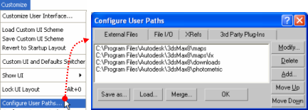
Invoking the Configure User Paths dialog box
On the Configure System Paths dialog box:
Click the 3rd Party Plug-Ins tab.
Click the Add button — the Choose Directory For New Entry dialog box will open.
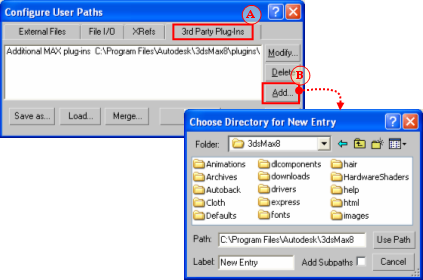
Invoking the Choose Directory For New Entry dialog box
On the Choose Directory For New Entry dialog box:
On the Folder drop-down list, select the folder containing the BigWorld exporter plug-in for your 3ds Max version, e.g. bigworld\tools\exporter\3dsmax2011.
On the file list, select visualexporter.dle.
On the Label field, type 'BigWorld exporters'.
Click the Use Path button — the Configure System Paths dialog box will be reactivated, listing BigWorld's exporter plug-in.
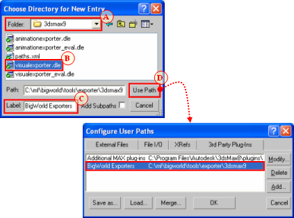
Setting the Choose Directory For New Entry dialog box
The BigWorld plug-in allows you to export Maya visual and animations created with versions 2008, 2009, 2010 and 2011.
Its features and installation steps are described in the sub-sections below.
The Maya Visual and Animation Exporter is a plug-in that exports mesh and animation data respectively to the .visual and .animation formats used by the BigWorld engine.
The visual exporter portion exports meshes, skinned meshes, transform nodes, BSP trees, hard points, portals and morph targets, and can also generate tangents and binormals for normal mapping. The animation exporter portion exports node animations and morph animations.
This version supports:
Static Models
Static Models with Nodes
Normal Models
Animations
Mesh Particles
Custom BSPs
Custom Hulls
Bump Mapping
Morph Targets and Animation
Custom node hierarchies.
In order to access the Visual and Animation Exporter plug-in, set the Export dialog box's Files Of Type drop-down list box to BigWorld Asset (*.*), as illustrated below:
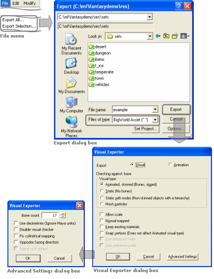
Invoking the Visual and Animation Exporter plug-in
The list below describes the components of the Export All Options dialog box:
Export
Sets the type of file being exported.
Visual
Specifies that the objects should be saved into a .visual file.
Animation
Specifies that the objects should be saved into a .animation file.
Visual type
Sets the type of visual being exported, and hence what information to save.
Animated, skinned
Specifies that the plug-in should export everything as is, i.e., every piece should be exported as a separate object, and all transform nodes and morph targets should be exported.
This option should only be used for visuals that have moving parts, either skinned or separate moving parts.
This option does not generate BSP trees from the meshes. If you want a (static) BSP tree for an animated object, then you will have to create a custom one.
Static
Specifies that the plug-in should combine all meshes into one, discarding all transform nodes and modifiers, and generating a BSP tree for the combined mesh (unless there is a custom one in the current scene).
This option should be used for shells and other static objects placed in the scene.
Static with nodes
Specifies that the plug-in should combine all meshes into one, exporting all transform nodes.
This option is similar to the option Static, except in that it will export all transform nodes for the scene
Mesh particles
Specifies that the plug-in should allow these meshes to be sorted when rendered, so that alpha blending works correctly. Each individual object in the scene is exported as one particle, in the format used by the mesh particle renderer.
There is a limit of 17 particle meshes exported for each mesh particle object.
Visuals exported using this option can be used as a particle system in Particle Editor. For details, see Renderer Properties sub-panel.
Allow scale
Indicates that the object should be exported with scale keys in it.
If you wish to use scaling animations, then you have to export both the visual and the animation with this option enabled.
Normal mapped
Specifies that the plug-in should create additional data to be used for normal-mapping the model.
This option must be checked to use a normal-mapped material on the model.
Keep existing materials
Specifies that the plug-in should keep changes to material made in Model Editor.
This option must be checked if you are overwriting a previously exported model, and want to keep material changes made in Model Editor.
Use reference node
Indicates that the animation should be exported with a node hierarchy different from the one in the current Maya file.
Once this option is checked, the Select Reference Hierarchy File dialog box is displayed, where you can select the visual file with the desired node hierarchy. For more details, see Exporting custom node hierarchy.
Snap vertices
Specifies that the plug-in should snap the vertices of all geometry to the nearest tenth of a millimetre.
This option has been added primarily to support the new use of portals — because the grid and axis alignment restrictions have been removed for portals, snapping portals to the nearest tenth of a millimetre can pull portals off bounding box or hull boundaries.
This option does not affect geometry exported when the Visual Type drop-down list box is set to Animated.
Strip reference prefix
Specifies that the plug-in should strip the model name prefix from the names of the animation nodes when using referenced models inside Maya.
When animating a model in Maya that uses a reference to a rigged model, the name of the model will be prefixed to the name of each animated node. As a result the node names of the original model will not match those of the animation, so the animation will not affect the model. By selecting this option, the model name will be stripped from the names of the animation nodes so that the node names in the visual file match those in the animation file.
Advanced Settings dialog
Bone count
Specifies the number of bones used by the Visual Splitter to divide any mesh up.
It is set to a default of 17 because that is the maximum that all BigWorld skinned shaders are designed to use. When a visual file uses more than 17 bones, the Visual splitter divides the object into 17 or less bone segments.
Only change this field if you have created shaders that support a different number of bones.
The field's maximum value is 87, which is the upper limit of BigWorld vertex format.
Use decimetres
Specifies that Maya units are interpreted as decimetres (1 unit = 10 decimetres) rather than metres.
Disable visual checker
Specifies that the plug-in should not check the exported model against the visual rules. A
Fix cylindrical mapping
Specifies that the plug-in should try to use an alternative method for generating texture space vectors used for normal mapping.
This option must be checked if there are artifacts along seams when using normal-mapped shaders.
Opposite facing direction
Specifies that the model has been modelled facing in the incorrect direction and that it should be rotated by 180 degrees so that is appears correctly inside the engine.
Scene root added
Specifies that the model already has a dummy scene root added by the artist. If not selected, a scene root will be added automatically so that the correct node gets examined as the itinerant when testing for the “Is Movement” action inside the BigWorld engine. This option provides support for customers with manually added dummy scene roots, therefore not requiring assets to be altered.
A — The rules are defined in file bigworld/tools/exporter/resources/visual_rules.xml. For details, see Validation rules.
The BigWorld Shelf contains useful a number of useful tools which help in asset production.
These shelf buttons are briefly described in the list below, a more extensive description can be found in the content creation manual.
- — Triggers a File - Export BigWorldAsset on
selected objects. If nothing is selected an Export All is
performed.
- — Adds the Portal attribute to the object's
face currently selected.
- — Adds the Exit attribute to the object's
face currently selected.
- — Adds the Heaven attribute to the object's
face currently selected.
- — Adds the Custom Hull attribute to the
selected object.
- — Adds the BSP attribute to the selected
object.
- — Attaches a hardpoint object to the selected
object. If nothing is selected the hard point is placed at the world
origin.
- — Points the normals of an objects selected
vertices away from a second helper object.
- — Adds hitbox objects to the selected
skeleton components.
- — Creates a skeleton_collider.xml file from
hitboxes in the scene.
- — Divides objects that are too big to export
into smaller exportable pieces.
- — Exports multiple models and shells as a
single prefab.
The requirements for creating in 3ds Max the game assets to be used in BigWorld Technology are covered in the document Content Creation Manual (accessible via World Editor's, Model Editor's, and Particle Editor's Help → Content Creation menu item, or directly by opening the bigworld/doc/content_creation.chm file).
In order to use the plug-in, you need to update your environment variables and Maya's plug-in settings. To do that, follow the steps below:
Note
The steps below are the same for all supported versions of Maya, only folder names for the latest version of Maya are shown
Add the BigWorld exporter folder as an additional plugin path to Maya:
Open Maya.env, e.g. My Documents/maya/2011/Maya.env.
Add the BigWorld exporter path to the MAYA_PLUG_IN_PATH variable, e.g. MAYA_PLUG_IN_PATH = C:/mf/bigworld/tools/exporter/maya2011.
Note
Each installed version of Maya can point to its appropriate version of the BigWorld exporters.
Copy the BigWorld's export script and userSetup script to the Maya folder:
Open Windows Explorer.
Navigate to the folder bigworld/tools/exporter/maya2011.
Select the visualfileexporterscript.mel and userSetup.mel files.
Copy the files to the My Documents/maya/2011/scripts folder.
Update Maya's plug-in settings:
Open Maya.
Select the Window → Setting/Preferences → Plug-in Manager menu item — the Plug-in Manager dialog box will be displayed.
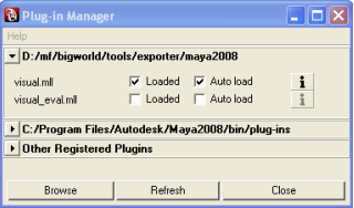
Plug-in Manager dialog box
Select the Loaded (to load the plug-in for the current session) and Auto Load (to load it automatically on startup of future sessions) check boxes.
Click the
 button — the Plug-in Information dialog box will be
displayed.
button — the Plug-in Information dialog box will be
displayed.The bigworld/tools/exporter/maya2011/visual.mll file should be listed.
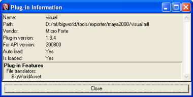
Plug-in Information dialog box
Click the Close button to return to the Plug-in Manager dialog box.
Click the Close button to return to Maya.
After carrying out these steps, you are ready to export your objects and animations to the .visual and .animation formats used by BigWorld.
Some of the BigWorld Shelf components require that the BigWorld exporters and userSetup script have been installed. For details see Installing the Maya exporters).
Copy BigWorld's shelf to the Maya shelves folder:
Open Windows Explorer.
Navigate to the folder bigworld/tools/melscripts/src/shelf.
Select the shelf_bigworld.mel file.
Copy the file to the My Documents/maya/2011/prefs/shelves folder.
Copy BigWorld's shelf icons the Maya icons folder:
Navigate to the folder bigworld/tools/melscripts/src/icons.
Select the all the icon bitmaps
Copy the files to the My Documents/maya/2011/prefs/icons folder.
Copy BigWorld's Maya Python scripts to the Maya shelves folder:
Navigate to the folder bigworld/tools/melscripts/src/scripts.
Select the contents of the folder bw_add_bsp.py, bw_add_customhull.py, bw_add_hardpoint.py, bw_add_hitbox.py, bw_common.py, bw_create_exit_portal.py, bw_create_standard_portal.py, bw_create_heaven_portal.py, bw_export_prefab.py, bw_object_divider.py, bw_munge_normals.py, bw_export_asset.py, and bw_create_skeleton_collider.bmp.
Copy the files to the My Documents/maya/scripts folder.
Copy the resources needed for the python scripts to Maya's project folder:
Navigate to the folder bigworld/tools/melscripts/resources/assets.
Select the contents of the folder hardpoint_helper.bmp, maya_hard_point.mtl, and maya_hard_point.obj.
Copy the files to the My Documents/maya/projects/default/assets folder.
Navigate to the folder bigworld/tools/melscripts/resources/textures.
Select the contents of the folder AID_BSP.bmp, AID_exitportal.bmp, AID_hportal.bmp, AID_portal.bmp, and AID_Hull.bmp.
Copy the files to the My Documents/maya/projects/default/textures folder.
Open Maya — you should see the BigWorld's tab in the shelf area (if that option is selected in Maya), and the icons displayed below (for details, see BigWorld shelf).
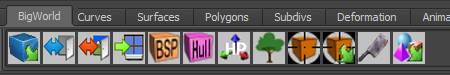
BigWorld shelf
The batch export script can automatically export multiple 3dsMax and Maya assets from a given source directory and all its subdirectories to a destination directory.
Searches through all sub folders of the Source directory and creates a list of all ".max" (3d Studio Max), ".mb" (Maya Binary) and ".ma" (MayaASCII) files.
Duplicates the hierarchy of the Source directory at the destination directory if the folders don't already exist.
Launches 3dsMax from the command line and passes it the list of .max files to be exported using a function in 3dsMax's startup script.
Assets with "animation" in their file path will be exported as .animation files otherwise a .visual export is performed.
Launches Maya from the command line and passes it the list of .mb files to be exported using a procedure in Maya's userSetup.mel startup script.
Writes all exported files to a log file created in the Source folder.
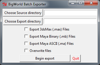
BigWorld batch exporter
Before using the batch exporter check the following
Ensure all source (.max, .mb) files and all destination (.visual, .primitive, .model, .animation) files are backed up with source control before using the batch exporter.
3d Studio Max and Maya are installed.
Both 3dsMax and Maya executable paths are entered in the System Environment Variables.
The BigWorld Maxscripts installed using bigworld_maxscripts_v1.5.mzp or later. The maxscript installer can be found in "bigworld\tools\maxscripts\" and instructions on how to install them, found in the content_creation.chm
The userSetup.mel script containing the bigworld_batch_exporter procedure should be been placed into "Documents and Settings\User\My Documents\maya\versionNumber\scripts". If you have an existing userSetup.mel script you can simply append the contents of the above file to the existing file.
BigWorld exporters installed and paths.xml set up correctly.
Sometimes it is useful to create an animation where the node hierarchy in the scene is different from the one that the model was exported with. This usually occurs when there are two elements in the scene, and you want to link them, then move them together.
The example below illustrates such a scenario:
When a character steps onto a little boat, you want both the character and the whole boat to dip down where the character's foot steps on.
To accomplish this, the character is linked to a rotating box used as a handle to rotate the whole boat, since this is easy to animate in 3ds Max.
But if this animation were exported with the node hierarchy in the current 3ds Max file, then the rotation would be lost, since that node is not normally in the hierarchy of the visual.
By exporting the model using the node hierarchy specified in a visual file, the resulting animation will look the same in the game engine as it does in 3ds Max or Maya.
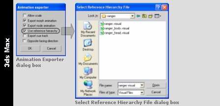
3ds Max
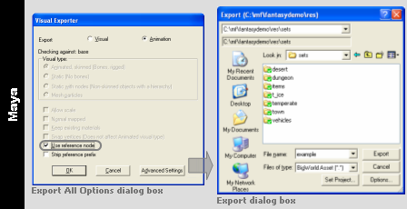
Maya
Before exporting the visual, the Visual Exporter plug-in validates it according to a set of rules defined in the bigworld/tools/exporter/resources/visual_rules.xml file.
The format of the visual_rules.xml file is as follows:
<visual_rules.xml>

  *<rule>
     <identifier>              id                                </identifier>
    ?<parent>                  parent_id                         </parent>
    ?<exportAs>               [normal|static|static with nodes]  </exportAs>
    ?<path>                    folder                            </path>
    ?<filespec>                file_matching_criteria            </filespec>
    ?<minSize>                 .f .f .f                          </minSize>
    ?<maxSize>                 .f .f .f                          </maxSize>
    ?<maxNodesPerRenderSet>    integer                           </maxNodesPerRenderSet>
    ?<maxTriangles>            integer                           </maxTriangles>
    ?<minTriangles>            integer                           </minTriangles>
    ?<portals>                 true|false                        </portals>
    ?<portalSnap>              .f .f .f                          </portalSnap>
    ?<portalDistance>          .f                                </portalDistance>
    ?<portalOffset>            .f                                </portalOffset>
    *<hardPoint>               hard_point_name                   </hardPoint>
    ?<checkUnknownHardPoints> [true|false]                       </checkUnknownHardPoints>
   </rule>

</visual_rules.xml >
bigworld/tools/exporter/resources/visual_rules.xml file format
The plug-in determines which rule to use based on the visual's target path and file name — it will search through all matching rules (ordering the rules based on the length of the value for the path tag — from the longest to the shortest), and use the first matching one (with either no filespec tag, or with one that matches the filename using standard wildcard matching).
The list below describes the tags in the visual_rules.xml file:
checkUnknownHardPoints
Specified if hard points not specified in the set of hardPoint tags should be flagged as error.
exportAs
Specifies how to save the visual.
Can have the following values: normal, static, or static with nodes.
fileSpec
Matching criteria (using wildcards) specifying the visuals for which this rule applies to.
This option is not inherited via the parent tag.
hardPoint
Name of the hard point that the visual must have.
The set of hard points to check against is the one formed by all hard points mentioned in all parents.
This tag may be defined multiple times for the same rule.
identifier
Name of the rule.
maxNodesPerRenderSetA
Maximum nodes allowed per renderset, i.e., how many bones each geometric element is allowed to use for skinning.
maxSizeA
Maximum size of the visual in metres.
maxTrianglesA
Maximum number of triangles in the visual.
minSizeA
Minimum size of the visual in metres.
minTrianglesA
Minimum number of triangles in the visual.
parent
Name of the rule from which to inherit options.
For each option, the plug-in will search up the hierarchy until it finds a match for it.
The path and fileSpec options are not inherited.
path
Resource folder which visuals this rule applies to.
This option is not inherited via parent tag.
portalDistanceA
Number of which the distance between the origin and the portal must be a multiple of.
portalOffsetA
Number of which the centre of the portal must be a multiple of on the portal plane.
portals
Determines if the visual may have portals.
portalSnapA
Number of which the bounding box of the portal must be a multiple of.
A value must be specified for each dimension.
A — A value of zero indicates that the option should not be checked.
Table of Contents
When creating large worlds in a multi-user environment, it is necessary to have a mechanism in place that controls the access by multiple world builders to the same space at the same time.
World Editor has built-in support for concurrent access, provided by its lock server bwlockd. It allows various users to edit the same space simultaneously, without conflicts.
When using the lock server, you will need to lock the regions of the world that you want to edit, so you have exclusive access to it
To use the Lock Server (also called BWLockD) in World Editor, some steps must be followed both on the server and on the client machines.
The following sub-sections describe these steps.
To enable concurrent editing of the world without conflicts, the BWLockD service (the Lock Server) has to be running. It should be run on a Linux server.
There is a script at
bigworld/tools/server/install/bwlockd.sh that can
be used to install the BWLockD service. Run the following command as
root in the bigworld/tools/server/install
directory.
# ./bwlockd.sh install
This will install the lock server init-script into
/etc/init.d/bw_lockd and install symlinks for the
/etc/rc*.d directories, such that the lock server
starts up at boot.
By default, the log file is at
/var/log/bigworld/bwlockd.log. Check the log for
a text message saying the daemon is listening on port 8168.
You can edit the installed
/etc/init.d/bw_lockd to tune the behaviour of the
lock server. In particular, useful variables to change are:
BIND_IP: the interface address the lock server binds toPORT: the port the lock server listens onLOG_OUTPUT_PATH: the output path for the log, by default this is set to/var/log/bigworld/bwlockd.logBW_LOCKD_DATA_DIR: the directory for the state files used in BWLockD.
As a system service, you can query the running state of the Lock Server.
# /etc/init.d/bw_lockd status
You can also run the lock server from the command line in the
foreground. There are various command-line options as the
--help output shows:
usage: bwlockd.py [options]

options:

  -h, --help            show this help message and exit
  --daemon              run process in the background (daemon mode)
  -I BIND_IP, --bind-ip=BIND_IP
                        IP/hostname of interface to bind to (default all
                        interfaces)
  -p BIND_PORT, --port=BIND_PORT
                        port to listen on (default 8168)
  --pid=PID_FILE
                        default daemon PID file (default "bwlockd.pid")
  -o OUT_FILE, --output=OUT_FILE
                        default daemon output file (only applies to non-daemon
                        mode, default "bwlockd.log")
  -v, --verbose         verbose output (only applies to non-daemon output,
                        daemon output is always verbose)
  --history=HISTORYPATH
                        output a history file that contains recent lock server
                        operations in XML format
  --data-dir=DATADIR
path to the data directory If you run the Lock Server from the command-line, you can pass
the --history option for the daemon to output a history
file, which contains a list of recent operations that the Lock
Server has processed. This is useful for debugging in conjunction
with the logging output. By default, no history file is
created.
In the event that you remove a space and recreate it before all clients have relinquished their locks on the old space, you may need to clear the locks and restart the lock server.
BWLockD maintains its state in files with the
.computer suffix for each workstation that has ever
created a lock. Each .computer file is an XML file, such as the one
below.
<?xml version="1.0"?>
<hostname>
    <space>
        <name> space_name </name>
        <lock>
            <rect> left top right bottom </rect>
            <username> username </username>
            <desc> lock_description </desc>
            <time> timestamp </time>
        </lock>
        <lock>
            ...
        </lock>
        ...
    </space>
    <space>
        ...
    </space>
    ....
</hostname>
|
|
|
|
|
|
|
|
|
|
For each space the given host has ever locked, there is a
space element that contains a name element
for the space, and multiple lock elements that describe
the locks that the workstation has currently acquired. Each lock
element has a rect element describing the lock rectangle,
who locked the region described by the username element,
the lock description entered when the lock was made in the
desc element, and the lock time in the time
element.
It may be necessary to clear locks manually by remove sections
from the .computer state files. For example, if a space
is removed and a new space is recreated with the same name, any
existing locks on the old space will be applied incorrectly to the new
space.If modifying the state files is required, you should shut down
the lock server, make your changes, and restart the server.
The PySVN library is used by svn_stub.py to interface with Subversion.
There is some additional configuration when using Subversion
server hosted using the svn+ssh scheme. This is not
required for the svn, http or
the https schemes. As an example of this, you may
have a Subversion URL
svn+ssh://developer@repository/srv/repos/.
In this case, there is a user called developer with
an account accessible by SSH on machine called
repository, and the repository is located at
your_game/trunk/srv/repos/,
and the trunk branch is at the top-level called
trunk.your_game
The Subversion version control stub uses the PySVN client, but
by default, the it has no way of authenticating automatically with
your server over SSH. We supply the authentication mechanism by using
PuTTY and its associated utilities PuTTYgen and PLink. To download
these tools, go to
http://www.chiark.greenend.org.uk/~sgtatham/putty. The
documentation for PuTTY can be found on that site as well.
Use PuTTYgen to generate a key-pair to use when authenticating
to a Subversion server hosted over SSH. This key-pair can be saved
away on the client machine somewhere memorable (it will be saved into
a file with a .PPK extension by default). Part of
the output of the key-pair generation will be a string that can be
used in a SSH authorized_keys file. This string
will need to be added to the user's
.ssh/authorized_keys on the machine hosting the
repository.
PuTTY can also protect the key-pair so that a passphrase is needed to use it. It also comes with a authentication agent called Pageant that you can use to keep decoded keys in memory so that key-pairs that are protected can be used after only unlocking them once per session. Refer to the PuTTY documentation for more details.
Subversion has a per-user config file that can usually be
located in the user's directory under Application
Data\Subversion\config. A new option needs to be added to
the [tunnels] section that calls the PLink
executable with the key file that you created in PuTTYgen. For
example:
[tunnels]
ssh=C:\Program Files\PuTTY\plink -i C:\...\keypair_file.ppk
The link can be tested by running a command such as svn update on a working copy already checked out (using TortoiseSVN, for example) using the svn+ssh scheme.
The path to the Perforce command line client is specified in the
P4_PATH module variable in
bigworld/tools/worldeditor/resources/scripts/p4_stub.py.
World Editor can be configured to use BWLockD server as follows:
Open World Editor's options file - bigworld/tools/worldeditor/options.xml (for details on this file's grammar, see the document File Grammar Guide's section options.xml → World Editor).
Update / add the following section as a child to the root node:
<bwlockd> <use> true </use> <host>
server_name:server_port</host> </bwlockd>The server_name is the name of the computer running BWLockD server, and server_port is an optional extension used to specify a particular port, which defaults to 8168. For additional information on changing the port BWLockD server listens on, see above in Server.
NavGen can be configured to use BWLockD server as follows:
Open NavGen's options file
bigworld/tools/misc/navgen_settings.xml(for details on this file's grammar, see the document File Grammar Guide's section navgen_settings.xml).Update / add the following section as a child to the root node:
<bwlockd>
server_name:server_port</bwlockd>The server_name is the name of the computer running BWLockD server, and server_port is an optional extension used to specify a particular port, which defaults to 8168. For additional information on changing the port BWLockD server listens on, see above in Server.
Update / add the following section as a child to the root node:
<standalone> false </standalone>
Use of the BWLockD server can be temporarily disabled by setting this tag to true.
The Lock Server supports the use of stubs for version control systems, which can be defined in World Editor's configuration file options.xml(for details on this file's grammar, see the document File Grammar Guide's section options.xml → World Editor.).
If no version control system stub is defined, then World Editor will use the default resources/scripts/svn_stub.exe for Subversion support. We also provide a p4_stub.exe script for Perforce.
Important Note: You can use any executable file or any file that has an associated default program as a stub. The provided stub exe files are compiled from python files in the same folder with same name by using py2exe. For more details visit py2exe's website at www.py2exe.org. If you want to use .py file directly, you have to ensure that .py file is associated with a Python interpreter. The Python installer on Windows will do that automatically.
A stub must support following commands:
addfile
Syntax:
<stubname>addfile<filename>AAdds the text file to the repository.
addbinaryfile
Syntax:
<stubname>addbinaryfile<filename>AAdds the binary file to the repository.
removefile
Syntax:
<stubname>removefile<filename>ARemoves the file from repository.
commitfile
Syntax:
<stubname>commitfile msg<filename>[ ,<filename>]* ACommits the files to the repository (the commit operation is recursive).
updatefile
Syntax:
<stubname>updatefile<filename>[ ,<filename>]* AUpdates all indicated files.
updatefolder
Syntax:
<stubname>updatefolder<foldername>Recursively updates all files in the indicated folder.
refreshfolder
Syntax:
<stubname>refreshfolder<foldername>ARecursively refreshes the status of all files in the indicated folder.
managed
Syntax:
<stubname>managed<file_or_folder_name>AReturns 1 if the file or folder is managed by the repository, or 0 otherwise.
A — filename may include the wildcard character * (asterisk).
In order to be able to share your spaces with other world builders, you need to follow a few simple steps. If the new space is created while World Editor is connected to bwlockd, the whole space will be locked for editing automatically, but if the space is created while World Editor is disconnected, the whole space will not be locked for editing.
When you create a new space while connected to the lock server, you need to follow these steps in order to share the space:
Go to Project mode, by clicking the Project Tool toolbar button —
 — (for details, see Toolbar).
Make sure that World Editor has successfully connected to the Lock Server.
Click anywhere on the space.
Enter a commit message and click on Save and Commit, and wait for the source control operation to complete.
On the other hand, if the space was created before connecting to the lock server, you will need to follow these steps:
Go to Project mode, make sure that World Editor has successfully connected to the Lock Server.
Select any area inside the space using click-and-drag.
Enter a descriptive message and click the Lock Selected Chunks button. Note that even if you select only one chunk, the whole space will be locked because it hasn't been committed yet.
Finally, if the space is not under source control, enter a commit message and click on Save and Commit, and wait for the source control operation to complete.
Once these steps have been completed, it will be possible for other world builders to get the space using the source control tools and then lock/unlock areas of the space to work on it simultaneously. For more details please refer to Locking an area.
While in Project mode, you can see the locked regions of the space. The red regions correspond to chunks locked by other world builders, while the blue indicates editable regions.
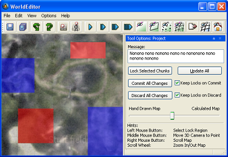
World Editor displaying editable regions in blue and non-editable regions in red
Note
As the mouse is hovered over a locked region, a tooltip is displayed with information on that lock, such as user, machine, date/time, chunk ID and lock message.
To enable or disable displaying non-editable areas shaded in red, select the General Options panel's Shade Read-Only Areas check box (for details, see General Options panel).
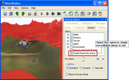
Non-editable areas shaded in red
To lock an area for editing, follow the steps below:
Click the Project Tool toolbar button —
— to activate the Project
mode.Make sure that World Editor has successfully connected to the Lock Server.
World Editor tries to connect to bwlockd upon startup, using the settings specified in bigworld/tools/worldeditor/options.xml. (for details on this file's grammar, see the document File Grammar Guide's section options.xml → World Editor).
If it did not connect successfully, then the Message field will contain the text "failed to connect to bwlock, you cannot use the related functionality", and the Lock Selected Chunks, Commit All Changes and Discard All Changes buttons will be disabled.
Click-and-drag over the area that you want to lock for editing.
The selected area will be shaded, indicating the chunks that will be locked and editable. Around that area, an area shaded in light grey will be displayed, indicating an area that will be locked but non-editable.
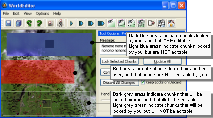
World Editor displaying information about chunks' lock and edit status
The actual editable area of a locked region is smaller by 1 chunk around the border. This is necessary to prevent tearing in the terrain that may occur if two people edit adjacent terrain chunks to different heights.
In the Message field, type a text indicating the reason for the lock.
This message will be displayed on a tooltip when other users hover over the locked area in World Editor while in Project mode.
Press the Lock Select Chunks button.
The selected chunks and the ones surrounding it will be shaded in blue, to indicate the success of the operation.
This process can be repeated many times if you want to lock an irregular area.
Once the world is complete, you will have to perform a pass over it to fill in the details in between previously locked sections.