Mesh LOD Theory
 Material LOD Theory
- Node LOD Theory
- Exporting the LOD components
- Implementing the LOD
Mesh LOD TheoryMaterial LOD TheoryNode LOD TheoryExporting the LOD componentsImplementing the LODLevel of Detail (LOD) can be used on models in BigWorld to increase game performance.
The biggest improvement in performance can be achieved by decreasing the number of draw calls performed by the engine. That means replacing a model that has multiple materials with a simplified single material model as it moves away from the camera. If your highest LOD model is already using a single material, then it is probably not worth adding a LOD unless its polycount is extremely high (>3500).
The LOD process involves directly swapping more complex models with simplified versions, and is handled automatically by the game engine based on the model's distance from the camera. SuperModel, the part of the engine responsible for drawing complex models, preserves animations and tints down the LOD chain.
The BigWorld engine can benefit from material, mesh and node LOD:
 Material LOD – requires the artists
to reduce the number of different shaders applied to the lower LOD level models. (This is the most important LOD.)
Material LOD – requires the artists
to reduce the number of different shaders applied to the lower LOD level models. (This is the most important LOD.)
Mesh LOD –
involves the artist creating a simplified version of the model by reducing the
polygon count. This should only be performed when polycount is extremely high or Material LOD is performed.
Node LOD – achieved by removing the
influence of chosen nodes from the further LOD model. This should only be performed when polycount is extremely high or Material LOD is performed.
 Mesh LOD Theory
A good guideline is to halve the number of polygons on each LOD level, until you reach less than a thousand polygons. Any further reductions can actually harm game performance.
This will not work for all models, but is a good place to start.
For example:
| LOD | Polygon count |
Distance (in metres) |
|---|---|---|
| 0 | 7,000 | 0 - 20 |
| 1 | 3,500 | 20 - 60 |
| 2 | 1,500 | 60 - 140 |
| 3 | 750 | 140 - 300 |
Example LOD settings
Optimising the object densityTo optimise object density, follow the steps below:
1 Load the Warrior_LOD.max example file.
2 Unhide and select the mesh_torso component
from the previous lesson, then in the Modifier List, clear the
Physique modifier.
Physique deactivated
3 Make a clone copy of it, called mesh_torso_LOD,
then select the original mesh_torso again and activate its Physique
modifier. Keep the copy in the scene and hide the original mesh.
 The reason for turning off Physique
first is that copying a mesh while this modifier is activated will cause parts
of the mesh to collapse.
The reason for turning off Physique
first is that copying a mesh while this modifier is activated will cause parts
of the mesh to collapse.
4 Delete the Physique modifier completely from the
copied mesh, using the Remove Modifier From The Stack
( ) button.
5 Enter Sub-object mode and begin reducing the mesh detail of the copy until about one-third the polygon count of the original mesh remains.
You can do this by using the polygon editing tools in either editablepoly or editablemesh modes – by welding and collapsing vertices together, thereby simplifying the mesh detail.
You can also use the multires modifier if you are using 3ds Max 4 or later.
Reduced density in torso for LOD
As you reduce vertices, the texture
mapping coordinates will adopt the new mesh form, and may look wrong when viewed
up close. This is OK as long as it is not too obvious in the size at which the
LOD is intended to be viewed. Otherwise you may have to readjust the mapping to
fit the new shape.
Zoom the viewport out periodically as you work, to assess whether the mesh detail is obvious or not. The idea is to keep the overall shape of the object intact, especially the silhouette or profile. Remove any minor detail areas that are not noticeable when viewed from a distance.
6 Unhide the mesh_legs, and again make a copy,
with the Physique modifier deactivated, and name the new copy
mesh_legs_LOD.
7 Remove the Physique modifier from the copy, and in Sub-object mode, reduce the density to about one-third the original polygon count.
Reduced density in legs for LOD
8 Repeat this process again for the arms and
head components, naming the copies mesh_arms_LOD and
mesh_head_LOD, respectively.
Reduced density in arms for LOD
Reduced density in head for LOD
9 Depending on your requirements, you may wish to repeat the process for a number of different LOD distances. Ideally, LODs should reduce the number of polygons by half. So, a 3,000-polygon character should have 1,500-, 750-, and 300-polygon LOD versions.
Material LOD TheoryAt further distances, effects of numerous complex shaders become negligible, and only serve to weigh down the performance of the engine.
It is therefore advisable to apply a reduced set of simple shaders to distant LOD models.
For example, the base LOD (LOD0) of a typical character may have
three separate material types, say metal, skin and
hair, with each using a different shader and referencing several
texture maps (Diffuse map, Normal map, Reflection map).
At LOD3, the character may only require a single simplified
shader that only references the diffuse texture, therefore increasing engine
performance.
Node LOD TheoryWhen removing the influence of bones from your lower-polygon LOD models, it is best to remove those bones that will not be providing any visible benefit at a distance.
For example, the vertices within the fingers, which at higher LODs would be controlled by several finger nodes, can be reduced to a single hand node when viewed from a distance.
This provides a performance boost for the engine, because it no longer has to transform all those vertices when the fingers animate.
Although the lower-polygon model still uses the same animations as the parent
LOD, it still provides a boost to the engine. That is because the vertices of
the fingers in the child LOD are not being influenced by finger bones.
Node LOD can be taken to extremes: the furthest LOD model of a character may only be represented as ten or so pixels on the screen - at this distance, the model needs as few as three bones to convincingly reproduce the leg movement action when walking.
Skinning with reduced linksFollow the steps below:
1 Unhide all LOD meshes that you created, and save them to separate 3ds Max files along with the biped structure.
For the purpose of this lesson, it is possible to rig the character only using certain bones. In not assigning any vertices to a bone, the engine will ignore it – this is useful in conserving memory when LODing out a character.
Biped at highest LOD |
Reduced links in the Biped structure for |
 You may also wish to attach some of
the segmented parts as one piece at the furthest LOD. Since you are using fewer
bones to rig the mesh, more of the mesh can be incorporated into the 17-bone
limit.
You may also wish to attach some of
the segmented parts as one piece at the furthest LOD. Since you are using fewer
bones to rig the mesh, more of the mesh can be incorporated into the 17-bone
limit.
2
At this level of detail, you should
not need to bother using the vertex weights feature for blending.
Exporting the LOD componentsFollow the steps below:
1 Make sure the hard points are attached to the appropriate links on the reduced biped structure.
2 Export the model to somewhere appropriate – in this
example we have chosen res/characters/avatars/torsos.
Export each component separately (with its own hard points) to the
correct folders, using the prefix name lod_.
For example, name the exported
mesh_torso_LOD component as lod_torso in the
torso folder.
LOD components and hard points exported
Implementing the LODFollow the steps below (make sure you have exported all the LOD versions that are going to make up your LOD tree):
1 Open ModelEditor.
2 Use the Asset Browser to load your LOD0
model (the model to be used at closest camera distance). For demonstration
purposes, we will use the torso.model made in the previous
lesson.
3 In the LOD panel, select torso.model
in the Model list.
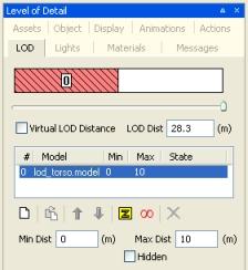
4 Click the Add New LOD
( ) button – the
Open dialog box will be displayed.
) button – the
Open dialog box will be displayed.
5 In the Open dialog box, select the
lod_torso.model file, then click the Open button.
The new LOD lod_torso.model will then appear in the
model list, and an initial Extent value of 10 will be applied to
the torso.model.
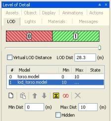
6 If you drag the Camera/LOD slider back and
forth, the camera distance changes, and the model swaps from
torso.model to lod_torso.model.
The LOD Dist field represents the distance between the model and the game camera. The model will remain in use until the value for that model is reached, then the next LOD model is loaded. If the model is closer to the camera, a more detailed model is loaded. Similarly, if the model moves away then a less detailed model is loaded.
7 Select the torso.model entry in the Model
list, then zoom the viewport out until the model is about half the size, and
finally click the Use the current camera distance
( ) button to set the value.
Readjust the value to 50 using either the slider or the LOD Dist field.
There are many ways to adjust the minimum and maximum values of LOD models. We indicate a number of them below.
8 Now do the same for the lod_torso.model, with a
value of 100.
9 In the viewport, zoom in and out. You should see the model swap from the highly-detailed version to the low LOD version.
Model swapping to less detail
When the viewport is zoomed out past the
lod_torso.model's distance of 100 metres, the model
disappears – this is because there are no child models below it
in the model list. Because torso.model is above
lod_torso.model in the model list, it is considered to be the
parent LOD model. If you do not want lod_torso to disappear
at 100 metres, then set the maximum distance to a higher value.
10 Save the model file for the torso, to add the LOD torso using the current distance extents.
11 Repeat this process for the legs, arms and head LOD models, starting with the high-detail versions as the parent models.
Copyright 1999-2011 BigWorld Pty. Ltd. All rights reserved. Proprietary commercial in confidence.