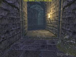
Shells are modularised objects built in a 3d application that are designed
to snap together in WorldEditor.
Their main purpose is to exclude geometry (including the terrain) from being
rendered by the game engine when the player is inside a room,
thereby potentially increasing the frame rate performance.
 Using shells will improve the performance of your game.
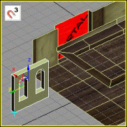
Shells also provide an efficient method for level building, since you
can simply auto-snap them (middle click) together to create entire rooms, streets or
corridors.
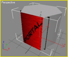
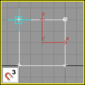
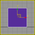
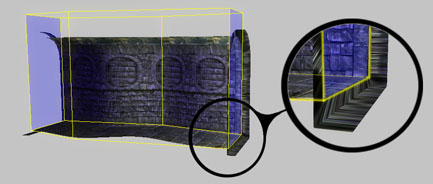
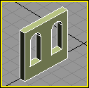
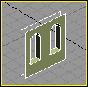
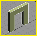
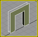
Shells don't have to be inorganic and square. The 3D geometry
that defines the explorable space within the shell can be any shape you wish,
providing it stays within the bounds of the shell’s custom hull (if a
custom hull is used) or bounding box.
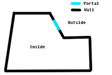
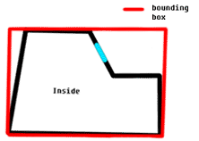
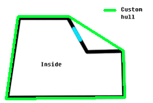
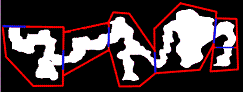
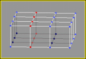
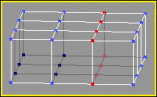
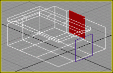
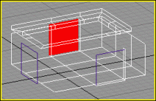
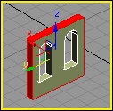
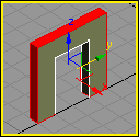
The diagram below illustrates one such implementation of shell design. The
explorable space (white) can be any shape. The custom hull (red) must
be convex.
The shells will automatically snap together in WorldEditor at the
portals (blue). It is important that you make the explorable areas at
the portal boundaries match each other, otherwise there will
be an obvious transition between shells.
Shells also allow for a more customisable lighting environment
than the outside world. For more information on lighting shells see the
lesson Add Lights to the World.
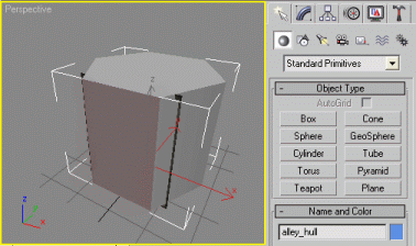
Shells consist of up to three unique parts:
 portals
custom hull (optional)
game geometry
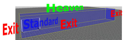
Portals are basically windows into a shell – they tell the game engine
when it can see into the next shell.
There are three types of portals, each allowing the engine to see in a different
direction:
 The type of material or texture
assigned to each portal is irrelevant. The textures assigned to
the portals are there for visual identification purposes only (they can be found in
The type of material or texture
assigned to each portal is irrelevant. The textures assigned to
the portals are there for visual identification purposes only (they can be found in bigworld\doc\tools_tutorial_examples within the path helper_maps

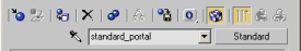
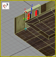
Standard/inter-shell portals allow the direct connection of one shell to
another, providing a two-way passage for the player to move through. When two
shells are connected (or resolved), the inside of one shell can be seen when
viewed from the other, and vice-versa.
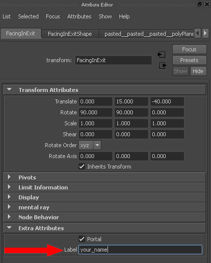
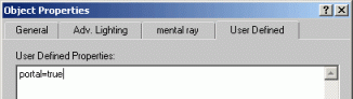
In 3ds Max, the tag line "portal=true" must be added to the Properties dialog box under the Object Properties→User Defined tab for that portal. To add a Standard portal flag to
your portal geometry in Maya, use the BigWorld Shelf's Add Portal button
( ).
).

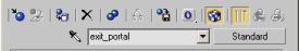
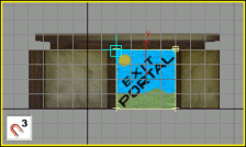
Exit portals allow a two-way passage from the inside of a shell to the outside terrain. When the
player is inside the shell, the terrain (outside) will be visible to the player, and vice-versa.
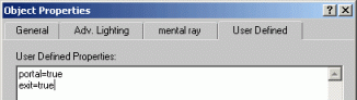
In 3ds Max,the tag line "portal=true" followed by
"exit=true" on a new line must be added to the Properties dialog box under Object Properties→User Defined tab for that portal. To add an Exit flag to your portal geometry in Maya, use
the BigWorld shelf's Add Exit Portal button
( ).
).
Exit portals (green) must be used whenever there is an indoor-to-outdoor
transition.

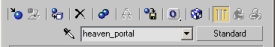
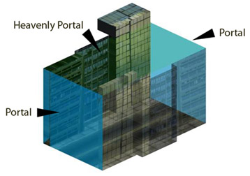
Heavenly portals are essentially one-way Exit portals. They allow all external objects to be rendered from the view of the internal shell. They do not allow the internal shell to be rendered when viewed from outside. Heavenly portals also have the unique feature that they let the sunlight in.
The tag line "portal=true" followed by "heaven=true"
on a new line must be added to the Properties dialog box under Object
Properties→User Defined tab for that portal. To add a Heavenly flag to
your portal geometry in Maya, use the BigWorld shelf's Add Heavenly
Portal button ( ).
).
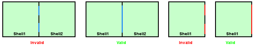
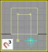
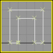
1 Portals must lie on the surface of a bounding box, or
of the custom hull (if one is used).
2 Portals must be convex. They cannot be concave.

Portals must be convex
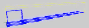
Hulls are a way of defining an artificial bounding box of a shell. The shell's
bounding box or hull defines what objects lie within it, and is used to cull
outside objects. Hulls are not a requirement of a shell – if a shell model is exported
without a custom hull, then the model's bounding box is used.
Using custom hulls simplifies the work of making building shells. If you define a custom hull
then it is very easy to ensure that your portal lies on its surface. If you use the
object's bounding box, a single stray vertex on the shell could offset the bounding box,
making it difficult to place the portal on the bounding box's surface.
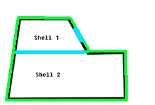
Below are two instances where a hull would be useful.

In the example above, the shell's bounding box (red) cannot be used as the
hull, because the blue portal would not be on the boundary of the shell. In this
case a custom hull matching the surface of shell1 is required.

In the example above, the shell1's bounding box (red) defines the blue object
within Shell2 as belonging to Shell1. If a hull was
used (green line), then the blue object would clearly not belong to
Shell01.
Hulls must be convex geometry,
so the yellow line cannot be used as a hull boundary.
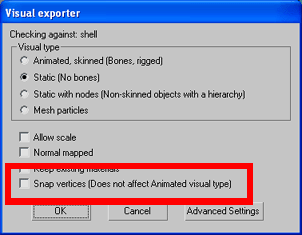
When exporting a shell with a portal that is not aligned to an axis (as
in the example above) you may need to turn the exporter option Snap vertices to OFF.
The Snap vertices option will force a portal's vertices to snap to the
nearest tenth of a millimeter. This is usually a desirable feature when creating portals that
are aligned to an axis. However, when a portal is not axis-aligned it can cause the portal to
be pulled off the surface of a hull or bounding box resulting in the following error.
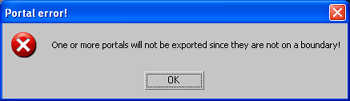
If you get the following error, try turning Snap vertices to OFF.
If the error persists, your portal is probably positioned incorrectly on the surface of your shell.
1 Custom hulls must be convex. They cannot be concave.
2 Custom hulls are identified by the suffix "_hull", for example "insertname_hull"

Custom hulls must be convex.
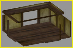
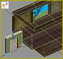
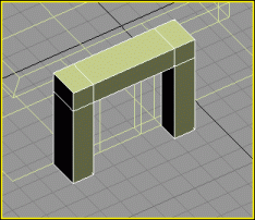
The geometry of the shell makes up the artistic content of the shell; its walls, floors, archways
and pillars.
Just remember that if you haven't used a custom hull, altering the game geometry can affect the
bounding box position, which may result in portals being lost because they no longer lie on the surface of the bounding box.
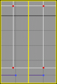
1 The explorable space of the shell should lie within the bounds of the custom hull (if one is used).
In the diagram below, the player P (red) in the right image would probably experience strange culling anomalies because
he has moved outside the bounds of the custom hull (black).
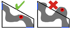
Keep the explorable space within the custom hull.
Although the following tutorial was performed in 3ds Max, the same principles
apply for those creating shells in Maya. If you are a Maya user, please take the
time to read through the tutorial.
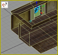
To model an example room, follow the steps below:
1 Open 3ds Max.
2 Load the example file room_shell.max from
the bigworld\doc\ools_tutorial_examples folder
The file can be found in tools_tutorial_examples\working_files\sets\shells\Room_shell.max.
3 Create a box at the origin in the
perspective viewport, with the following size (in generic units):
125 length x 110 width x 40 height (in generic units).
Segments of 3 length x 3 width x 1 height.
4 Change to a user viewport to see the home grid in an
isometric view.
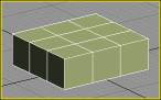
Created box with its segments
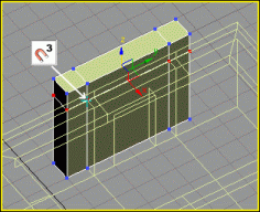
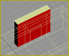
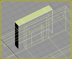
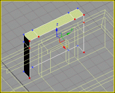
5 Convert the box to an Editable Poly.
6 In 3dsMax, use the Move tool to translate it 27.5
units in the Y-axis.
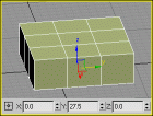
Box after translation in 3ds Max
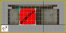
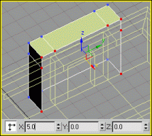
7 Create the first portal – a rectangle object will
be used to represent the portals that the BigWorld engine uses to snap together
different shells.
A In the front viewport, create a rectangular shape of
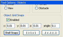
40x40 units using 3d grid snap.
B Apply an Extrude modifier to it, with a height
value of 0.
A 40x40 rectangle |
B Extruded rectangle |
C Using the grid snaps, move the shape to the box position
just beside the middle segments.
Moving the shape near the box, using grid snap |
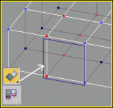
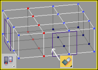
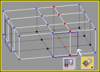
D Select box's middle-left row of vertices.
A Select the box.
B Enter Sub-Object mode.
C Select the middle row of vertices on the left.
Middle-left row of vertices selected
E Set the reference coordinate system to Pivot Point
centre.
F Align middle-left row of box vertices to shape.
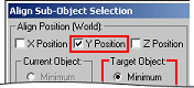
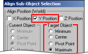
A Using the Align tool, click on the shape.
Aligning the vertices to the shape's left edge
B In the Align Sub-Object Selection dialog box,
select the X Position check box, and in the Target Object group
box, select the Minimum option button.
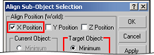
Align Sub-Object Selection dialog box
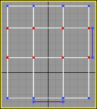
C The vertices should move in the x-axis, to the left edge
of the shape, as shown below in Top view.
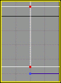
Top view showing vertices aligned
G Align the middle-right row of box vertices to shape.
Follow the same procedures as in step F with the right row of vertices, so that they also lie on the grid, but this
time select the Maximum option button in Target Object group box.
Middle-right of vertices selected |
Top view showing vertices aligned, using
the right side of shape as the target |
H Both rows of the middle vertices of the box should now
lie on the home-grid.
Top view showing vertices aligned to the grid
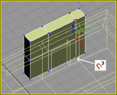
8 Create second portal
A Exit Sub-Object mode of the box.
B Select the shape.
C While holding Shift, click the shape, to
make a new copy of it.
D Move and snap the copied shape to the adjacent side of
the box, to absolute position [X: 60, Y: 40, Z: 20].
Shape copied and offset to absolute position
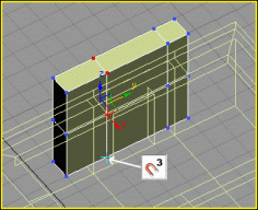
E Rotate the shape's orientation by 90 degrees in the
z-axis using Angle snap.
Rotating shape by 90 degrees
F Select the box.
G Enter Sub-Object mode.
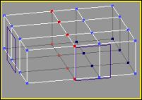
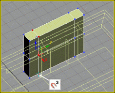
H Align the middle-left row of box vertices to shape.
A Select the middle-left row of vertices in line with the
second shape.
B Align the box's vertices to the
shape.
In the Align Sub-Object Selection dialog box, select the Y Position check box, and in the Target Object group box, select
the Minimum option button.
C The vertices should move to the left edge of the shape.
|
|
|
A Middle-left row of vertices is selected |
B Align Sub-Object Selection dialog box |
C Vertices moved to left edge |
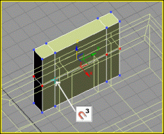
I Align the middle-right row of box vertices to shape.
A Select the middle-right row of vertices.
B Align the box's vertices to the shape.
In the Align Sub-Object Selection dialog box, select the Y Position check box, and in Target Object group box, select the Maximum option button.
C The vertices should move to the left edge of the shape.
|
|
|
A Middle-right row of vertices is selected |
B Align Sub-Object Selection dialog box |
C Vertices moved to left edge |
J From the top view, both rows of vertices should now lie
on the grid in line with the second shape.
Top view showing vertices aligned to the grid
At this point the room only needs an entrance, some sockets,
plugs, and portals.
The walls in this example have been
spaced a minimum of 0.5 metres away from the bounding box (outside edges) of the
shell – this is to allow room for doors to open inside walls, and prevent
zero-thickness walls in corners of shells.
Objects must be no larger than
100 metres (1,000 generic units) on any axis – this is the limit of object
size inside the BigWorld engine.
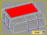
To create a ceiling height variation for the room, follow the steps below:
1 Enter Poly Select mode.
2 On top of the box, select the six polygons opposite the
second shape.
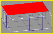
3 Using the Inset tool, scale the polygons inwards,
to create additional edges inside the original selection.
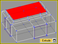
4 Using the Extrude tool, slightly raise the height.
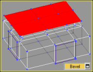
5 Using the Bevel tool, slightly scale the polygons
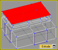
up and out.
6 Using the Extrude tool, raise an edge on the
rooftop, to complete the ceiling height variation.
7 You can now UV Unwrap the object and apply texture maps
to it.
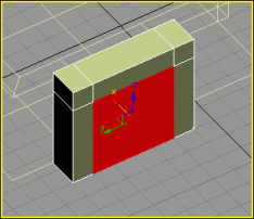
To create a socket for an exit hole, follow the steps below:
1 Enter Sub-Object mode for the "shell_room".
2 Create first portal
A Select the polygon next to the
first shape.
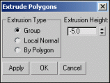
B In the Extrude
Polygons dialog, set Extrusion
Height to -5.0.
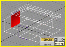
Original polygon |
Extrude Polygons dialog box |
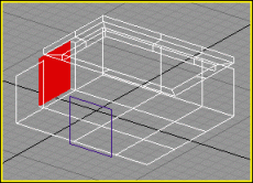
Extruded polygon |
C Completely detach the polygon, and
name it "portal_01".
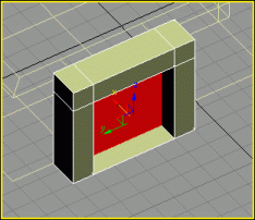
3 Create second portal
A Rotate the view so that the polygon next to the second shape is visible.
B Select that polygon and apply the same Extrude Polygon
settings as before.
Extruded polygon
C Detach this polygon and name it "portal_02".
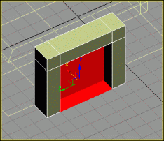
4 Create third portal
A Rotate the view back to see the
opposite wall.
B Select the polygon directly
opposite "portal_02"
C Apply the same Extrude Polygon settings as
before.
Opposite polygon extruded
D Detach the polygon, and name it "exit_portal".
5 Exit Sub-Object.
6 Delete the two rectangle shapes
previously created.
7 Assign textures to the portal
objects
A Select the two portal objects
named "portal_01" and "portal_02".
B Assign a portal texture to the
selected portals.
Inter-shell portal texture
C Select the "exit_portal"
object.
D Assign an exit portal texture to
it.
Exit portal texture
8 Assign properties to the portal
objects
A Select the "portal_01"
object.
B Right-click the selected object,
and in the quad menu select Properties.
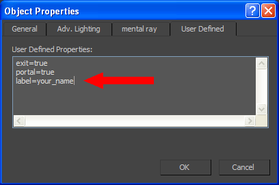
C In the User
Defined tab, type "portal=true".
3ds Max's Object Properties dialog box – Setting portal_01
D Select the "portal_02"
object.
E Set the same properties as for "portal_01".
F Select the "exit_portal"
object.
G In the User
Defined tab, type "portal=true"
and "exit=true".
3ds Max's Object Properties dialog box – Setting portal_02
Portals can be used to increase the rendering performance of geometry-rich
areas such as towns and cities. When designing a city it is important to take
into consideration how portals can be utilised.
It is important to understand how portals work in order to maximise their effectiveness.
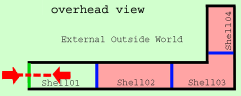
In Image 1 in the examples below, player P (red) is rendering the final shell (Shell3) because all the
portals (blue) are aligned.
A better design choice would be to include a second portal (as in Image 2). In this
example the player will not render shell4.
Shell geometry is not used to cull portal tests.
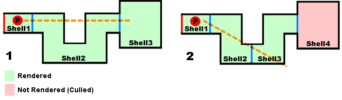
Umbra software can use shell geometry to occlude portals.
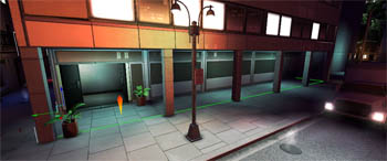
This type features narrow streets with high buildings and surrounding walls. The high walls and
tall buildings of this city type occlude vision into neighbouring areas, making
it ideal for using shells.
Sections of the city can be created as shells. Portals can be placed at
the end of streets and in archways.
Considerations
If the city contains tall
buildings that are to be seen from multiple shells, then these shells must use
heavenly portals as their ceiling.
Heavenly portals allow the outside world to
be rendered. Therefore the tall buildings must be outdoor objects and not belong
to any shell.
Because heavenly portals do
not allow players to see into a shell, players cannot look down into the city
from a high viewing position, such as a skyscraper – the heavenly portals
allow rendering one way (out), but not in.
This type of city should be surrounded with
a high wall, to prevent players looking into the city.
Shells can be snapped
together in WorldEditor, making town- and city-building fast.
Terrain geometry under the
city can be deleted to further increase rendering performance and prevent
Z-fighting.
This type features large streets with open areas such as markets and parks, with mostly small
buildings in which you can enter.
Shells can be used
to create the interior of houses and buildings.
It is very important to
create at least two shells for each building.
The first shell (an entrance hallway, set of stairs, or
reception room) allows the second more important and highly detailed room to
be culled using the portal method.
The longer the hall (and hence the further the two portals are
from each other), the bigger is the chance that the room will be culled from
outside. Most game designers will use a bent "L" shaped entrance way to
maximise portal culling. Multiple shells will help increase the probability
of culling the main internal shell.
Portal and shell visibility considerations
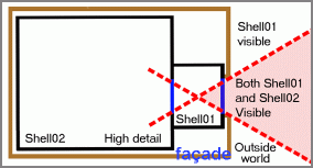
The outside of a shell (brown) is a standard model which we refer to as a façade.
Even though the façade geometry does not
overlap the shell, its pivot point might. This results in the 3d engine mistaking
the façade for an internal object belonging to that shell, and lighting
it as such. To ensure that façades light correctly, in WorldEditor's
Properties tab, set the outside only property to
True.
WorldEditor's Properties tab
Minimise the size of each portal
Because portal culling depends on portals lining up with each other and the
camera, the smaller the size of each portal, the greater the chance that culling
will occur. For this reason, it is best to make the portal dimensions extend just beyond
the size of the geometry defining the doorway, window or entrance, and no further.
Sometimes no matter how carefully you make shells they do not
resolve together closely enough in WorldEditor to prevent players from seeing a small line
of "sparkles" between shell boundaries. This is due to floating point inaccuracies
from asset creation to display. The sparkly line visible in the picture below is a result of the outside world being visible
between two shells.
These sparkles are not only visually unappealing, they can result in decreased game performance due to bad culling. See the section on how to create assets when using Umbra
There are two ways to solve this problem:
add a flange to your shell
that extends past the boundaries of your shells, or,
use an object to fill the gap
between shells – we call these objects plugs.
To prevent sparkles (light from outside penetrating gaps between shells) a
flange can be added to each shell. The flange should be wider than the visible
interior of your shells and overlap with flanges on connecting shells.
Because the flange sits outside the
portal (blue), you will need to create a custom hull (yellow). This is because
the exporter will not recognise portals unless they are on the shell's bounding box,
and the creation of the flange would move the bounding box, preventing the portal from being recognised.
Side view of the fantasy demo asset dun_highpassage_4x.visual designed with a flange (inset)
The other way to prevent sparkles (gaps) between your shells
is to hide the gaps with objects. We call these objects "plugs". Plugs are just standard models that hide any visual gaps
between shells. They do not have any special specifications and are not
a requirement for shell design.
In this part you will create plugs for the standard portal and
the exit portal created earlier in this lesson.
To build a window plug that fits the standard portal socket,
follow the steps below:
1 Create a rectangle shape of 40x40
units over "portal_02" in the left viewport.
Rectangle shape created over portal
2 Create archways.
A Inside the rectangle shape, create an archway shape for the window.
B Make a copy of the archway shape, so that two windows occupy the rectangle shape.
C Collapse the rectangle shape to an editable spline.
D Use Attach on the rectangle and on both archways,
to combine them all into one shape.
E Weld all the vertices.
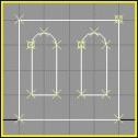
Rectangle shape with archway windows
3 Apply an extrude modifier to the window shape with a
height value of units.
Extruded window shape
4 Remove polygons outside the object.
A Collapse the window plug to an editable poly.
B Enter Sub-Object mode.
C Select and delete the polygons around the outside of the
extruded object.
Outside polygons in red |
Object with outside polygons removed |
D Exit Sub-Object mode.
5 Name the object "plug_windows".
6 Using 3D snap with vertex mode, move the
plug_windows object over portal_02 and inside the
socket you created previously in the lesson.
 |
 |
Plug object moved into position using vertex snaps |
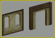
To build a window plug that fits the exit portal socket,
follow the steps below:
1 Create a rectangle shape of 40x40 units over
exit_portal in the left viewport.
Rectangle shape created over exit portal
2 Create archways.
A Use the line shape tool to draw an archway shape
over the rectangle that you just created, using the grid snaps as a guide.
B Attach the line shape to the rectangle and trim the
segments at the bottom to close the shape.
C Weld all vertices.
 |
 |
Archway with vertices attached and welded |
3 Apply an extrude modifier to the shape with a
height value of 5 units.
Extruded window shape
4 Remove polygons outside the shape.
A Collapse the shape to an editable poly.
B Enter Sub-Object mode.
C Select and delete the polygons around the outside only.
Outside polygons in red |
Object with outside polygons removed |
D Exit Sub-Object mode.
5 Name the object plug_doorway.
6 Turn on the 3D vertex snaps.
7 Move the plug_doorway object over the
exit_portal to fit neatly into the socket created.
 |
 |
Plug object moved into position using vertex snaps |
8 UV unwrap and apply texture maps to both
plug_windows and plug_doorway objects.
Texture-mapped window and doorway plugs
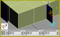
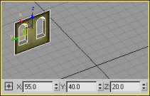
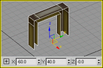
9 Build an entrance object to cover the outside doorway.
A Create a box next to the exit_portal with
the following settings:
World position: x=-65, y=40, z=0.
Dimensions (in units): length=60, width=10, height=50.
Segments: length=3, width=1, height=2.
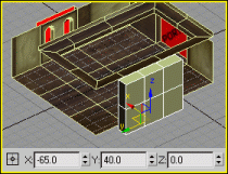
Box created with specific world position coordinates
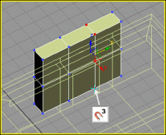
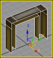
B Rotate the view until you see the exit_portal object.
C With the box still selected, convert it to an editable poly.
D Enter Sub-Object mode.
E Enlarge the slot for the opening.
1 Enlarge frame to the right.
Select the middle-right vertical row of vertices.
Using 3D vertex snap, move
them to the outside right corner of the exit portal socket.
 |
 |
Vertices snapped to the socket's right corner |
2 Enlarge frame to the left.
Select the middle-left row of vertices.
Using 3D vertex snap, move them to the outside left
corner of the exit portal socket.
 |
 |
Vertices snapped to the socket's left corner |
3 Enlarge frame upwards.
Select the middle-horizontal row of vertices.
Using 3D vertex snap, move
them up, to the top of the exit portal socket.
 |
 |
Vertices snapped to the top of socket |
F Enter polygon mode.
G Select the bottom and inside polygons, and delete them,
including any isolated vertices.
Inside and bottom polygons selected |
Inside and bottom polygons deleted |
H Enter vertex mode.
I Select the inside border vertices and move them 5 units
relative in the X-axis.
Before moving |
After moving |
J Create the opening.
1 Rotate the view to the front of the entrance.
2 Enter polygon mode.
3 Select the middle polygon and extrude it inwards -10
units.
Before extruding |
After extruding |
4 While pressing Ctrl, select the bottom
polygon.
Now both the middle polygon and bottom polygon are selected.
5 Delete the selected polygons.
Middle and bottom polygons selected |
Middle and bottom polygons deleted |
6 You can now UV unwrap and apply texture maps to the
entrance object.
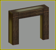
Texture-mapped entrance object
The finished 3ds Max scene should now contain a room object, a
windows plug, a doorway plug, and an entrance object for outside the shell.
This awning is typical of an outside area that rain should not penetrate. In the Urban demo this was achieved using a shell.
Shells can be used to create an outside area that is sheltered from the weather.
The outside only tag in Particle Editor will prevent particles from being rendered when inside a shell.
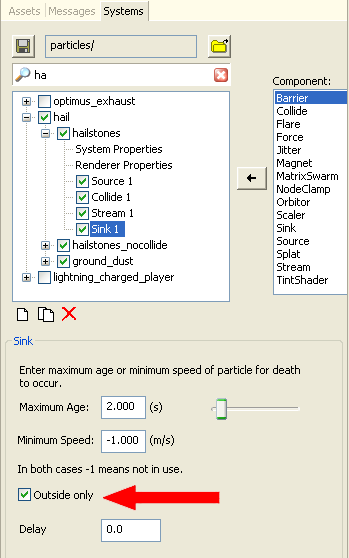
If you create a shell with exit portals on all sides of the shell and a heavenly portal it will appear as if the shell is an outside space yet it will still prevent particles tagged with Outside only from being rendered.
IMPORTANT: The heavenly portal will allow sunlight and time of day changes to effect the insides of the shell. The location of the heavenly portal is not important, it simply acts as a switch to allow light into the entire shell or not.
This image shows the portal setup used in the shell office_exit.visual
IMPORTANT: The base of the shell must have some geometry or a custom BSP. If no bsp is used an entity will not be able to navigate through this shell.
Note the custom bsp. Without this entities would fail to navigate the shell
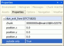
Sometimes, objects that exist on the border of exit portals (usually exit
plugs, and building facades) think they belong to the inside of a shell. These
objects will not light correctly and may appear dark during the day.
This can be fixed by forcing an object to be lit by outside lighting
only, from the Properties tab in WorldEditor.

Outside only property
Before and after setting the outside only property in WorldEditor
All art assets to be used in the BigWorld engine must reside in the resource folder your_game/res
or one of its subdirectories.
This includes bitmaps referenced by any shells or plugs you may create. If your
shell or plug is referencing bitmaps from another location other than the /res directory, you must move
those bitmaps into the resource folder (or one of its subfolders).
To reference the room and plug texture maps, follow the steps below:
1 Open Windows Explorer.
2 Navigate to your game's resources
folder res/sets/town.
3 Under folder town,
create folder shells and another folder for plugs.
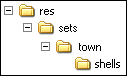
Folder shells contains copies of the finished bitmaps
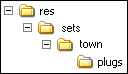
Folder plugs contains copies of the finished bitmaps
5 Open the 3ds Max Bitmap/Photometric Path Editor
or the Asset Tracker utility.
6 Reassign the materials to the folders just created.
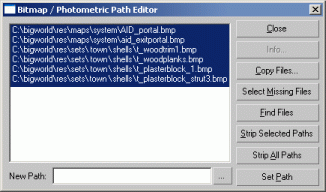
3ds Max utility for reassigning bitmaps
For shells to export correctly all portals must exist on a 0.1 Metre
(1 standard 3ds Max unit) grid. Otherwise the shell will not comply with
the exporter's visual rules.
To export "shell_room", follow the
steps below:
1 Hide all plugs.
2 Hide the entrance.
3 Make sure that all portals are
visible in the scene.
4 Select menu item File→Export.
5 In the File
Browser dialog:
Navigate to the new folder shells.
In the File
Name field, type "shell_room_exit".
In the Save As
Type drop-down list box, select the entry "Visual
Exporter (*.Visual)".
Click Save.
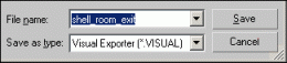
File Browser dialog
6 In the Visual
Exporter dialog:
In the Visual
Type group box, select Static
option button.
Clear the Allow
Scale check box.
Check Bumpmapped
if your shell is going to use normal maps. Otherwise leave it unchecked.
Click OK.
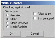
Visual Exporter dialog
To export the plugs, follow the steps below:
1 Centre the plugs to the origin,
for proper grid snapping with the shell.
2 Hide all visible elements in the
scene.
3 Unhide the "plug_windows"
object.
4 Make sure that the home-grid is
displayed.
5 Select the plug object and centre
it to the world origin using absolute coordinates, but keep the base of the
object flat on the grid.
Original plug object |
Plug object centred to the origin |
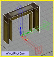
6 In the Hierarchy
panel, under Adjust Pivot,
activate the Affect Pivot Only
option.
7 Centre the pivot point at the
world origin.
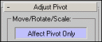
Affect
Pivot Only option
Original plug object |
Plug object pivot-point-aligned to the origin |
8 Select menu item File→Export....
9 In the File
Browser dialog:
Navigate to the new folder plugs.
In the File
Name field, type "plug_windows".
In the Save As
Type drop-down list box, select the entry "Visual
Exporter (*.Visual)".
Click Save.

File Browser dialog
10
In the Visual Exporter
dialog:
In the Visual
Type group box, select Static
option button.
Clear the Allow
Scale check box.
Clear the Bumpmapped
check box.
Click OK.
Visual Exporter dialog
11
With the "plug_windows" object selected,
select menu item File→Save
Selected.
12
Save the object to its own 3ds Max file.
13
For the "plug_doorway" object:
Repeat the process above (steps 1 to 12).
13
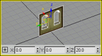
For the "entrance" object:
A Unhide, then select the "entrance"
object.
B Edit the pivot point and offset it
by 5 units in the X-axis relative.
entrance object's original pivot point
|
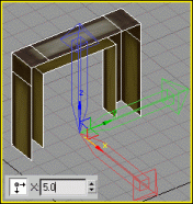
entrance object's pivot point offset
|
C Using absolute coordinates, centre the object to the
world origin on the home-grid.
entrance object's original position
|
entrance object centred at the world origin
|
D Export the "entrance" object.
Follow steps 8
to 10, saving the object in the same folder
as the plug objects.
Copyright 1999-2011 BigWorld Pty. Ltd. All rights reserved. Proprietary commercial in confidence.
 What is a shell?
  Components of a shell
  What is a Shell?