Table of Contents
- 11.1. Configuring the space to use NavGen
- 11.2. NavPoly Generator menu items
- 11.3. NavPoly Generator status bar
- 11.4. NavPoly Generator keyboard shortcuts
- 11.5. NavPoly Renderer keyboard shortcuts
- 11.6. NavPoly Generator mouse controls
- 11.7. NavPoly Renderer mouse controls
- 11.8. Statistics dialog box
- 11.9. Cluster Generate dialog box
- 11.10. Navpoly Info dialog box
- 11.11. Navpolys, vertices and adjacency
- 11.12. Generating the navmesh on multiple machines
- 11.13. Generating the navmesh
- 11.14. Moving entities
- 11.15. Changing settings
- 11.16. Discontinuous navmesh
NavGen is one of the BigWorld tools used to create the navigation mesh. The navigation mesh is a space-covering connected set of polygonal prisms. It allows an entity to navigate between any two arbitrary points in the scene.
Note
The other tool provided by BigWorld to generate a navmesh is the Offline Processor, which uses Recast. For more details, see Offline Processor.
After you have created a space with World Editor, or changed a chunk, you can open NavGen and generate the navigation mesh.
NavGen uses the exclusive locks acquired in World Editor with the Lock Server (bwlockd). — for details, see Lock Server (BWLockD).
When you open NavGen, you are presented with two main windows and an error log:
-
NavPoly Renderer — Displays the 3D scene of the space.
-
NavPoly Generator — Displays the output from the navpoly generation.
-
Error Log — Outputs information messages and error messages.
The main windows both use the following colours to draw the chunk elements:
-
Blue — Navpoly
-
Red — Selected navpoly
-
Black — Empty space
Both windows are illustrated below:
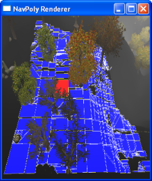
Navpoly Renderer
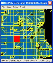
Navpoly Generator
A navpoly might be selected in either window, and is rendered in red in both of them
Double-clicking a navpoly on either window invokes the Navpoly Info dialog box, with height, and vertex coordinates and adjacency information on the selected navpoly. For more details, see Navpoly Info dialog box.
Each edge on a navpoly can be shared with the edge of an adjacent region. Alternatively, an edge may be marked as being adjacent to a different chunk. This means that movement between these two regions is allowed.
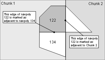
Navpoly edge demarcation
In order for NavGen to generate navmeshes for the chunks in a space,
the space must be properly configured. The
navmeshGenerator option in
space.settings must be set to
navgen. NavGen will also be used by default if the
navmeshGenerator option is not explicitly set.
Modifying this value will not automatically cause chunks to be dirtied, so
if a navmesh already exists, the next generation will have to be run in
overwrite mode. For details refer to Generating the navmesh.
If a space is opened that is not configured to use NavGen as its navmesh generator, NavGen will operate in read-only mode. It can still be used to inspect existing navmeshes for the space, but it will not be able to generate new meshes. For details, see the Inspecting the navmesh section.
The list below describes the menu items available in NavPoly Generator:
-
File → Open space
Used to open a space inside NavGen.
-
File → Open
Opens the Open dialog box, where you can select the adjacency map or chunk file that you want to load.
-
File → Remove all NavGen data
Removes the NavGen data for the current space.
-
File → Generate all
Generates the navigation mesh for all chunks in the space that have changed since the last generation.
-
File → Generate all overwrite
Generates the navigation mesh for all chunks in the space, regardless of whether it has changed since the last generation.
-
File → Cluster generate
Opens the Cluster Generate dialog box (for details, see Cluster Generate dialog box), which allows you to generate the navigation mesh in parallel (across multiple computers) for all chunks in the space that have changed since the last generation.
For details, see Generating the navmesh on multiple machines.
-
File → Exit
Quits the application.
-
View → Sets → All
Set all navmesh sets inside the current chunk to be visible.
-
View → Sets → None
Set all navmesh sets inside the current chunk to be invisible.
-
View → Sets → Individual Set Index
Toggle the visibility of individual navmesh set identified by the index.
-
View → Adjacencies
Toggles the visibility of grid point adjacencies as white lines overlaying the chunk.
These points are created during the flood fill phase of the generation of the navigation mesh — for details see Navpolys, vertices and adjacency.
Like BSP nodes, adjacencies will not be visible if the chunk was loaded from a chunk file; only when directly generated for a single chunk or loaded from a .tga file.
-
View → BSP nodes
Toggles the visibility of BSP nodes to a given depth of the BSP tree.
These nodes are created during the generation of the navigation mesh — for details see Generating the navmesh.
Like adjacencies, BSP nodes will not be visible if the chunk was loaded from a chunk file; only when directly generated for a single chunk or loaded from a .tga file.
The . (Period) and , (Comma) keys increase and decrease the depth displayed, respectively.
The BSP node is drawn as a polygonal prism with an additive colour. The list below describes how the BSP nodes will be displayed:
-
Blue
The node is completely traversable, i.e., it is a navpoly.
-
Green
The node is a combination of traversable and non-traversable regions.
-
Transparent
The node is completely non-traversable.
-
-
View → Polygon area
Toggles the visibility of the navpolys on both the Renderer and the Generator windows.
If selected, the navpolys in the chunk will be rendered in blue, and the selected one in red.
-
View → Polygon borders
Toggles the visibility of the borders of the navpolys on both the Renderer and the Generator windows.
-
View → Statistics
Opens the Statistics dialog box, with information about the chunk.
For more details, see Statistics dialog box.
-
View → NavPoly info
Opens the Navpoly Info dialog box, with information about the selected navpoly.
For more details, see Navpoly Info dialog box.
-
View → Rendered scene
Opens the NavPoly Renderer window (if it is closed) and brings it to the front.
-
View → Error log
Toggles the display of the Error Log dialog box.
-
Zoom → In on navmesh
Zooms in the chunk view in the NavPoly Generator window.
-
Zoom → Out on navmesh
Zooms out the chunk view in the NavPoly Generator window.
-
Chunk → DisplayA
Loads the navigation mesh for the chunk in which the camera currently is, and displays it.
-
Chunk → GenerateA
Generates the navigation mesh for the chunk in which the camera currently is, and displays it.
-
Chunk → Generate shrunkA
Performs the same operation as the Generate menu item (this item was implemented for previous versions, when multiple girths were not supported).
-
Chunk → ReannotateA
Reannotates the disconnected edges of the navigation mesh for the current chunk (annotation is the final step of navigation mesh generation).
Note
This functionality is now deprecated.
-
Help → Help
Opens the Help dialog box.
A — The shortcuts available for these menu items must be used in the NavPoly Renderer window. For details, see NavPoly Renderer keyboard shortcuts.
The status bar displays information about the current chunk. A typical status bar is illustrated below:

NavPoly Generator status bar
The list below describes the pieces of information displayed in the status bar, as they appear:
-
Mesh's girth label (in the example, Girth 0.5)
Girth label of the navigation mesh currently displayed, as configured in the file bigworld/res/helpers/girths.xml. For more details, see Changing settings.
-
Local chunk coordinates (in the example, Lpoint (2.61, 4.31))
Location of the mouse cursor in local chunk coordinates.
-
Global space coordinates (in the example, Point (-97.39, 4.31))
Location of the mouse cursor in global space coordinates.
-
Local navigation mesh coordinates (in the example, Grid (6,10))
Location of the mouse cursor in local navigation mesh coordinates.
In addition, when calculations are done (via Generate All, Generate All Overwrite, or Generate Cluster menu items — for more details, see NavPoly Generator menu items), the status bar displays the following information:
-
Number of chunk being processed (Text: Calculating chunk
n1ofn2)Number of chunks that have been calculated, and how many are to do in total.
During cluster generationA, the number of calculated chunks includes the number of chunks skipped by your computer (these chunks are calculated by other computers in the cluster).
-
Progress of calculation of current chunk (Text: Generation Status:
stage: Processedn1points (current stack sizen2))Rough estimate of how much calculation has been done in the current chunk.
There are usually about 40,000 points to process in a chunk.
A — For details, see Generating the navmesh on multiple machines.
The sections below list the keyboard shortcuts available for NavPoly Generator.
-
+ (Plus sign)
Zooms into the chunk view in the NavPoly Generator window.
Performs the same function as the Zoom → In menu item.A
-
- (Minus sign)
Zooms out of the chunk view in the NavPoly Generator window.
Performs the same function as Zoom → Out menu item.A
-
[ (Square left bracket)
Decreases the girth for which to display the navigation mesh.B
-
] (Square right bracket)
Increases the girth for which to display the navigation mesh.B
A — For more details, see NavPoly Generator menu items.
B — The available values for girth are defined in bigworld/res/helpers/girths.xml. For more details, see Changing settings.
The sections below list the keyboard shortcuts available for NavPoly Renderer.
-
Ctrl
Increases the navigation speed by a factor of 5. Can be used in conjunction with Caps Lock.
-
Caps Lock
Increases the navigation speed by a factor of 10. Can be used in conjunction with Ctrl.
-
Enter
Performs the same function as the Chunk → Display menu itemA.
A — For more details, see NavPoly Generator menu items.
-
! (Exclamation mark)
Generates the navigation mesh for the chunk in which the camera is, and displays it.
Performs the same function as the NavPoly Generator's Chunk → Generate menu itemA.
-
* (Asterisk)
Reannotates the disconnected edges of the navigation mesh for the current chunk.
Performs the same function as the NavPoly Generator's Chunk → Reannotate menu itemA.
-
, (Comma)
Increases the depth displayed of the BSP nodes.
To display BSP nodes, select the NavPoly Generator's View → BSP Nodes menu itemA.
-
. (Period)
Decreases the depth displayed of the BSP nodes.
To display BSP nodes, select the NavPoly Generator's View → BSP Nodes menu itemA.
-
@ (At sign)
Generates the navigation mesh for the chunk in which the camera is, and displays it.
Performs the same function as the NavPoly Generator's Chunk → Generate Shrunk menu itemA.
-
[ (Left square bracket)
Decreases the girth for which to display the navigation mesh.B
-
] (Right square bracket)
Increases the girth for which to display the navigation mesh.B
A — For details, see NavPoly Generator menu items.
B — The available values for girth are defined in bigworld/res/helpers/girths.xml. For details, see Changing settings.
The list below describes the mouse controls available for NavPoly Generator.
-
Left button click
Selects the navpoly.
-
Left button double-click
Opens the NavPoly Info dialog box for the selected navpoly.
For more details, see Navpoly Info dialog box.
-
Right button drag
Moves the navigation mesh in the direction of the mouse movement.
-
Scroll wheel rotate
Zooms the navigation mesh in and out, according to the direction of scroll.
The list below describes the mouse controls available for NavPoly Renderer.
-
Left button click
Selects the navpoly.
-
Left button double-click
Opens the NavPoly Info dialog box for the selected navpoly.
For more details, see Navpoly Info dialog box.
-
Right button drag
Rotates the camera in the direction of the drag.
This dialog box is accessed via the View → Statistics menu item (for details, see NavPoly Generator menu items), and displays statistics regarding the current chunk.
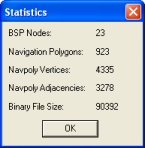
Statistics dialog box
The list below describes the information displayed in the dialog box:
-
BSP nodes
Number of BSP nodes in the navigation mesh.
These nodes are created during the generation of the navigation mesh — for more details see Generating the navmesh.
-
Navigation polygons
Number of navpolys in the navigation mesh.
-
Navpoly vertices
Sum of the number of vertices of all navpolys in the navigation mesh.
Most vertices will be counted more than once, since they might belong to more than one navpoly. This way, the number displayed for this field is the number of <vertex> tags present in the generated .chunk file for the chunk navigation mesh.
-
Navpoly adjacencies
Number of adjacencies of the vertices of all navpolys in the navigation mesh.
Note that adjacency is not generated for a vertex bordering an empty space.
-
Binary file size
Size of the navigation mesh in the .cdata binary file.
This dialog box is accessed via the File → Cluster Generate menu item, and displays options to run NavGen on the space across multiple machines (for details, see Generating the navmesh on multiple machines).
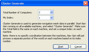
Cluster Generate dialog box
The list below describes the information displayed in the dialog box:
-
Total number of computers
Number of computers processing space data in parallel.
This number should be the same in all computers.
-
My index
Unique identifier for the computer processing space data.
This number should be unique.
This dialog box is accessed via the View → Navpoly Info menu item, or by double-clicking a navpoly on either window, and displays height and vertex coordinate and adjacency information for the selected navpoly.
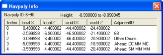
Navpoly Info dialog box
The list below describes the information displayed in the dialog box:
-
Navpoly ID
Integer pairs used to identify the navmesh. The first integer is its set index. The second integer is a unique identifier for the navpoly in the chunk.
-
Height
Vertical range of the navpoly prism.
-
Vertex table
-
Index
Vertex sequential number
-
Local x, Local z
XY coordinates of the vertex in local coordinates.
-
World x, World z
XY coordinates of the vertex in world coordinates.
-
Adjacent ID
ID of the element adjacent to the vertex.
The list below displays how the possible elements adjacent to the vertex are displayed:
-
Other navpoly in same chunk
Displayed as: Navpoly ID
-
Empty area
Displayed as: Blank
-
Chunk
Displayed as: Literal 'Other Chunk'
-
Obstacle
Displayed as: Literal 'Ahead: [S|M|R|C][S|M|R|C] [S|M|R|C][S|M|R|C] [S|M|R|C][S|M|R|C]'
The text after the literal contains information about obstacles ahead, 45° to the left, and 45° to the right of the vertex.
It consists of three pairs of obstacle information: the first letter of the pair contains information about the bottom half of the corresponding direction, while the second letter contains information about the top half of the corresponding direction.
The list below describes the possible values of the pairs' letters and the corresponding obstacle status:
-
S — Solid
-
M — Mixed
-
R — Reserved
-
C — Clear
For example, an Adjacent ID column with value of 'Ahead: SM SC MM' stands for the following information about obstacles and the vertex:
-
Ahead
-
Bottom half — Solid
-
Top half — Mixed
-
-
45º to the left
-
Bottom half — Solid
-
Top half — Clear
-
-
45º to the right
-
Bottom half — Mixed
-
Top half — Mixed
-
-
-
-
A chunk is divided into navpolys, which are convex polygons. The polygon indicates an area where it is clear to move. Therefore, if a room is completely empty, it will have a single navpoly. However, if it has a bench in the middle, then it will have four navpolys, to avoid covering the bench —i.e., there will be a hole in the passable area of that chunk. Entities can move around a navpoly, and between adjacent ones.
The polygons have a height too, so they are actually polygonal prisms. The navigation mesh works in 3D for scene elements such as staircases and overhangs. Even though it can be used for flying entities, enhancements are needed for better support.
For NavGen, a vertex is a continuous portion of the navpoly border that is adjacent to only one other navpoly, chunk, object, or empty space. It means that if one side of a navpoly is adjacent to 2 others, then that side has 2 vertices.
In the illustration below, note the following:
-
Navpoly 2 has one side that is adjacent to navpolys 6 and 7. NavGen will generate one vertex for each navpoly adjacency.
-
NavGen might generate a vertex with no adjacency for vertices that are bordering an empty space. For the portion of the side of navpoly 3 that is adjacent to an empty space, NavGen will generate 1 vertex, but no adjacency.
-
NavGen generates vertex data for each navpoly at a time. That means that vertices shared between navpolys in the same chunk are present in the resulting .chunk files twice — once for each navpoly. This excludes vertices that are adjacent to another chunk.
The illustration below shows an example of a chunk with 11 navpolys and 2 empty spaces, and a table with the number of vertices and adjacencies for each of them.
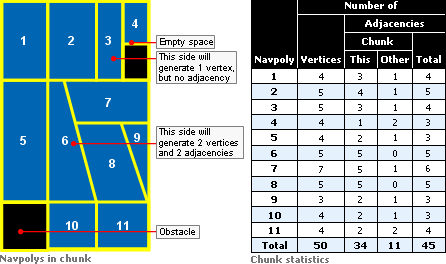
Navpolys In Chunk vs. Chunk Statistics
Running NavGen on large spaces can take some time to process. To reduce processing time, it is possible to divide the computation across multiple computers, each one working only on a subset of chunks (first make sure that each computer has an up-to-date copy of the space being calculated). It is best to use cluster generation in conjunction with a version control system, such as CVS or SVN.
Select the File → Cluster Generate menu item (for details, see NavPoly Generator menu items), then in the Cluster Generate dialog box (for details, see Cluster Generate dialog box), enter the number of computers that will be generating the cluster, and a unique index for each of them. The computers will proceed individually (there is no coordination between machines). To get the results from each computer back into one space use the version control system's check-in functionality (e.g., cvs commit). There should be no overlap between the computers over the changed files, so merging individual files should be unnecessary.
If you stop the process (because, for example, NavGen did not finish overnight and you wish to use the machines again), then you can continue the calculation process when convenient. In this case, NavGen will quickly skip over already calculated chunks.
Besides generating the navigation mesh for the whole space, it is also possible to generate it just for a specific chunk.
To do so, position the camera in the desired chunk, then select the Chunk → Generate menu item. This method of mesh generation does not display progress status.
When generating the navigation mesh for the space (via the File → Generate All or File → Generate All Overwrite menu item), the first chunk to be processed is the one where the camera is in. Upon completion of the chunk, the adjacent ones will be processed. Only chunks changed in World Editor since the last generation will be processed.
The generation process takes approximately 3 to 5 minutes per chunk, and if all chunks are being processed, then a real-time view of the progress is displayed in the window.
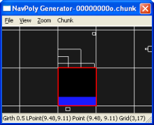
Progress of navigation mesh generation — Step 1
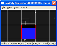
Progress of navigation mesh generation — Step 2
Once the navigation mesh has been generated, the results can be viewed on a chunk-by-chunk basis. In the NavPoly Renderer window, navigate to the desired chunk, then press Enter — this will display the navigation mesh for that chunk (for details, see NavPoly Renderer keyboard shortcuts).
For more details on the format of the generated .chunk files, see the document Server Overview's section Server Components → CellApp → Navigation System.
The process of generating the navigation mesh for a space is a time-consuming one, due to the amount of calculation necessary for a fast and efficient final product.
For completely flat chunks without obstacles, the generated mesh will be composed of a single large navpoly. But any other geometry requires an initial matrix of collision scene tests from each direction to every other one, followed by a BSP-based reduction scheme to arrive at the final navpolys. The time invested in creating an efficient mesh is greatly compensated by the result of a fast navigation through the space.
Please note that while this may seem slow, the time spent on adding scene elements to the world via World Editor will in most cases amount to much longer than the time taken to generate the navigation mesh for it. Furthermore, the navmesh generation can occur overnight
On the other hand, if you have written your own tools to auto-generate large parts of your world (and server-controlled entities can roam freely over those parts), then this equation could change. If that is your case, then contact the BigWorld support engineers so that they can guide you in auto-generating your world and the navigation mesh at the same time.
Based on terrain and other geometric information in the chunk files, NavGen creates the convex navpoly polygons in three main phases:
-
It flood fills each chunk, using client physics rules.
-
It uses a BSP algorithm to recursively subdivide the space and form convex polygonal prisms.
-
It then annotates the polygon edges and writes the results back into the binary .cdata files.
The following sub-sections describe this process in details.
The flood fill algorithm currently samples the chunk geometry using a grid of 0.5 metre resolution.
This is the default resolution, and whilst it is configurable via bigworld/tools/misc/navgen_settings.xml, it is ideal for human-sized entities, since a courser resolution would be less accurate, and a finer resolution would end up generating excessive navpolys. Also, since the same point in the grid may exist at several heights within each chunk (in case of elements such as tunnels and bridges), 16 grids are used to describe the connectedness of the scene in each chunk.
Within each grid, the movement is tested from each point on the grid to its eight neighbours. As an intermediate step, this information is saved to a TGA file (the file is saved in the folder specified by the option floodResultPath in bigworld/tools/misc/navgen_settings.xml). For more details, see Adjacency map filtering (blue).). NavGen also saves the origin point, the sample resolution, and the y-values for each grid point to the TGA header. This means that the polygons can be generated from the TGA file alone — the TGA file could be viewed with an ordinary TGA viewing program if only one grid was used.
The flood fill algorithm currently only allows bi-directional movements, i.e., movements allowed in only one direction — such as jumping off a cliff — are not accepted.
The algorithm also checks the hulls of neighbouring chunks. It stops flooding when it crosses to another hull (actually it stops flooding just after crossing). Thus, each chunk's grids slightly overlap another one by one flood movement unit, and as far as navpoly are concerned this is how chunk adjacencies are calculated. For more details, see Adjacency map filtering (blue).
The following points are the seed points for the flood fill:
-
Centre of the chunk.
-
Points along the perimeter of the chunk and its internal portals — they are moved in slightly towards the centre of the chunk along the portal plane normal.
-
Points where an entity has been placed in the scene.
Having multiple seed points is necessary in cases where a chunk is composed of multiple disjoint but internally connected regions.
After the calculation, each chunk will have a 3D bitmap representing an adjacency grid.
Smoothing filters are applied to this adjacency grid bitmap, to smooth it out and remove any artifacts that would lead to degenerate polygons.
In general, this step only removes connections — it does not add them. If the floodResultPath configuration option is defined in bigworld/tools/misc/ navgen_settings.xml, then TGA files are saved to that path. These files represent the states before and after filtering.
This step reduces the filtered adjacency grid bitmap into a set of convex polygonal prisms. The fewer resulting prisms the better, since less geometry will need to be loaded by the server during the game.
The basic approach is to sub-divide the space by generating a 3D BSP, until each leaf node is entirely traversable, (i.e., it presents no obstructions for navigating), or entirely non-traversable. It makes the process easier that all leaf nodes of a BSP are guaranteed to be convex (a nice side effect of this approach is that, given a point, the BSP could be used to quickly find its navpoly. Such feature is not currently implemented, because performance has not been an issue — and the BSP would take extra memory — but it is good to keep this ability in mind).
The heuristic for splitting the space has two goals:
-
Try to produce a balanced tree, by splitting the space near the centre.
-
Try to split the space along boundaries between traversable and non-traversable regions.
For each point in the region, if the point has an adjacency in one direction (e.g., north), but none along one of the neighbouring directions (e.g., northwest or northeast), then mark a possible split along the line from north to south. The split is given a value according to its distance from the centre of the region, and the split closest to the centre is chosen.
To make the tree more balanced initially, if the region is larger than the value of constant EVEN_SPLIT_THRESHOLD (defined in C++ source file src/lib/waypoint/ waypoint_generator.cpp, with a default value of 25 metres) in any dimension, then it is split in half along the shortest axis. In some cases, a vertical split must be made.
After having generated the BSP, the process of forming the polygons is simple, consisting of the following sub-steps:
-
Vertices are created wherever lines intersect.
The edge of a polygon will be split if it is adjacent to more than one polygon, since each vertex can have only a single adjacency.
-
If the resulting polygon is convex, then adjacent polygons are joined.
This sub-step is repeated until it is no longer possible to combine any polygons. Often, 50% of polygons can be joined.
-
Chunk adjacencies are calculated.
This sub-step calculates chunk adjacencies.
As mentioned in section Adjacency and height map calculation (from black to blue), chunks may overlap each other by one flood movement unit. This way, NavGen can use this information and determine that if both sides of an edge are inside the hull of a neighbouring chunk, then this edge is marked as adjacent to that chunk.
Note that the adjacency will be marked in the .cdata file as being related to a chunk, but not which one. This is because a space might be connected to another one in the server, in which case the adjacent chunk will not be assigned until runtime.
With help from the GPU, the edges of navpolys that are not adjacent to another one (i.e., adjacent to a non-traversable region) are annotated with the situation visible from that edge.
The scene looking out from that edge is rendered orthographically into an offscreen buffer and then analysed. The situation is represented with two bits for each of the top half and the bottom half of the screen.
The following list describes the possible values for these two bits:
-
Completely clear
The edge has visibility to the navpoly ahead of it, even though the navpolys are not adjacent.
Example: A chasm between the two navpolys.
-
Completely blocked
The edge has no visibility to other navpolys.
Example: A wall between the navpolys.
-
Partially blocked
The edge has visibility to some navpolys, but not to others.
Example: A tree between the navpolys, so some of them are visible through the branches.
This procedure is performed considering three directions for each edge (resulting in 12 bits of information per non-adjacent edge):
-
Straight ahead
-
45º to the left
-
45º to the right
The illustration below describes the assembling of the navpoly adjacent ID ABCDEF:
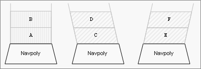
Assembling of navpoly adjacent ID field with value ABCDEF
The actual value stored in the .chunk file for the vertex's adjacent_ID field is the logical NOT of this 12-bit value, since BigWorld considers all negative adjacency values as meaning that none exists.
The purpose of annotation is to provide hints about the world to AI algorithms on the cell that go beyond simply what regions are traversable and which are not. At the moment, the method findCover is the only one that takes advantage of this situational information. Adding others, however, will be trivial if the need arises.
After generating the space's navmesh, you may want to examine the result. You can do this by doing the following:
-
In the NavPoly Generator window, select the View → Rendered Scene menu item (for details, see NavPoly Generator menu items) — this will move focus to the NavPoly Renderer window.
-
Inspect the navmesh
-
In the NavPoly Renderer window, navigate to the point of interest using either the keyboard or the mouse (for a compete list of keyboard shortcuts and mouse controls available in NavPoly Renderer, see NavPoly Renderer keyboard shortcuts and NavPoly Renderer mouse controls).
-
Display the navmesh by pressing Enter.
-
Navmeshes of different girths can be selected using the [ (left square bracket) and ] (right square bracket) keys.
-
The navmesh is displayed as a collection of blue polygons.
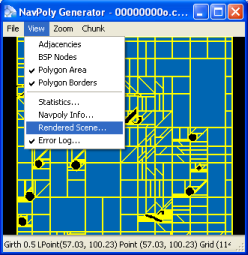
Generated navmesh — Navpoly Generator
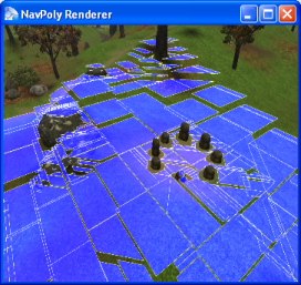
Generated navmesh — Navpoly Renderer
Once there is a navigation mesh for the space, you can use the Entity.navigate and Entity.navigateStep methods in cell scripts to move the entities. For more details, see the CellApp Python API's entry Main Page → Cell → BigWorld → Classes → Entity → navigate.
You should use the filter AvatarDropFilter on
the client for such entities. This is because the position sent by the
server is the top of the navpoly prism, which is dropped up to two
metres[2] to find the real position on the ground. This saves the
server from doing many ground position tests, and improves the client's
interpolation, so that interpolated positions can also look right. If you
do not use this filter, then the entities will hover slightly above
hills.
The settings for NavGen are stored in the bigworld/tools/misc/navgen_settings.xml file[3].
<navgen_settings.xml> <space> spaces/desert </space><bwlockd> server1:8168 </bwlockd>
<standalone> false </standalone>
<floodResultPath> \mf\fantasydemo\res </floodResultPath>
</navgen_settings.xml>
Example file bigworld/tools/misc/navgen_settings.xml
|
Space to load. |
|
|
World Editor Lock Server (bwlockd) control. For details, see Lock Server (BWLockD) |
|
|
Determines if NavGen should connect to a bwlockd server. |
|
|
Path where the pre-filter and post-filter TGA files are generated. For more details, see Adjacency map filtering (blue). |
NavGen also uses settings that are stored in a Girths file, located
at bigworld/res/helpers/girths/xml[4] by default. This file contains profiles for entity types
that will use each layer of the navmesh. For details, see Server Programming Guide's section Configuring Girth Information for Navmesh Generation.
The final space might contain areas that are not reachable on foot from other areas, examples might be the roofs of buildings, ledges, or pits.
Entities should be placed in islands of navigable terrain to ensure that their navigation mesh is generated. Also, be aware that unreachable areas that span multiple chunks will still have navmesh generated for them, even if there are no placed entities present.
[2] Navpolys cannot be taller than two metres
[3] For details on this file's grammar, see the document File Grammar Guide's section navgen_settings.xml.
[4] For details on this file's grammar, see the document File Grammar Guide's section girths.xml.
