Not all special effects should rely on a particle systems alone. Most of the
time, complex special effects require multiple particle systems, meshes, and animations, all perfectly timed.
For example, the effect seen in the first two frames below (used for the
player re-spawn) was made using an animated mesh, NOT a particle system. Only
the last frame contains a particle system.
Animated mesh special effect |
Animated mesh special effect |
Particle system special effect |
Special effects are coordinated via SFX files. SFX files are created by programmers and bring together the various components (particles, models, animation) for the final effect. It is very important to work alongside a programmer when creating complex visual effects.
The directory mf/fantasydemo/res/sfx contains all the special effects for the fantasy demo.
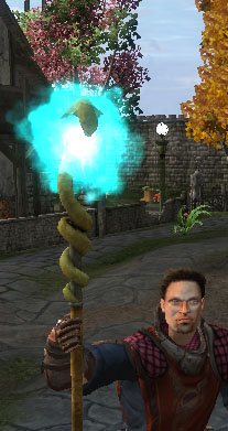
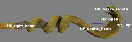
Let's take a look at the staff_idle.xml effect on the Ranger's magic staff by opening the file in Notepad.
This SFX file actually contains two separate effects named staff_particle 1A and staff_light 2A. These names are used to indicate which tags belong to which effect system.
The first thing to occur is the creation of the Actors, these are the objects that make up the special effect.
1a: The particle system staff_idle.xml
2a: A light with set radius and colour are created
1b: The particle is attached to HP_Snake_Neck
2b: The Light is attached to HP_Top
1c: The particle system is played
2c: The light is set to flicker
<SFXFile>
	<Actor> staff_particle 1A
  		<ParticleSystem>  particle/staff_idle.xml     </ParticleSystem></
	</Actor>

 	<Actor> staff_light 2A
  		<Light>
			<innerRadius>    2       </innerRadius>
			<outerRadius>    8       </outerRadius>
			<colour>    128 192 255 2558       </colour>
		</Light>
	</Actor>

	<Joint> staff_particle 1B
    		<Node> HP_Snake_Neck </Node>
	</Joint>

	<Joint> staff_light 2B
    		<LightSource> HP_Top </LightSource>
	</Joint>

	<Event> staff_particles 1C
    		<ForceParticle/>
	</Event>

	<Event> staff_light 2C
    		<Flicker>
				<amplitude>    0.1       </amplitude>
				<speed>    0.5       </speed>
	    	</Flicker>
	</Event>
</SFXFile>
For the purposes of this tutorial, we will create a particle system called
pollen, which will be placed near plants and flowers to give them
drifting pollen.
This particle system will consist of two particle sub-systems:
glows and colouredglows.
1 Open ParticleEditor.
2 In the Systems panel, click the
 to create a new particle system
– a new entry will be added at the bottom of the Particle List,
where the insertion point will be moved.
to create a new particle system
– a new entry will be added at the bottom of the Particle List,
where the insertion point will be moved.
3 Name the new particle system pollen.
4 New particle systems have a new sub-system
automatically added, named component – press
F2 and rename it glows.
5 Expand the glows sub-system – the
System Properties and Render Properties sub-system components
(created by default on new sub-system components) will be displayed.
6 Select the System Properties sub-system component
– the System Properties sub-panel will be activated.
7 In the System Properties sub-panel, set the
Capacity field to 30.
This field controls the number of particles that your particle
sub-system will spawn.
Please note the following:
 This example particle system
will be sprite-based, so you should now create your texture for the particle
sub-system, and save it in a folder appropriate for its use.
This example particle system
will be sprite-based, so you should now create your texture for the particle
sub-system, and save it in a folder appropriate for its use.
This example has a
pollen texture without an alpha channel, because we will set its
properties to Additive. We have made the surrounding base texture pure
black, as this will then be rendered transparent. We have then placed an
almost-white shape for the pollen in the centre of this image.
Leaving the pollen-shaped
section of the image almost colourless means that we can later tint the
colour of the texture with more effect via the Tint Shader sub-panel.
8 Select the Renderer Properties sub-system component
– the Renderer Properties sub-panel will be activated.
9 In the Renderer Properties sub-panel:
Select the Sprite option
button.
Specify the pollen texture
(first make sure that your current folder is correctly set, using the
 button).
Set the Blend Mode
drop-down list box to Additive.
 Using textures set to
Additive is generally less intensive for rendering, and therefore more
particle effects can be used in a single scene without increasing rendering
costs. However, the look of Additive settings may not always suit your
purposes.
Using textures set to
Additive is generally less intensive for rendering, and therefore more
particle effects can be used in a single scene without increasing rendering
costs. However, the look of Additive settings may not always suit your
purposes.
The Source component of a particle sub-system is
responsible for generating its initial position and velocity, among other
settings.
1 In the Systems panel's Component list box,
select the Source item, then click the
 button – this will add a
Source sub-system component to the particle's sub-system, and will
also activate the Source sub-panel.
button – this will add a
Source sub-system component to the particle's sub-system, and will
also activate the Source sub-panel.
2 Specify the particle sub-system's initial position and
velocity.
You can do this by manipulating the 3D gizmo, or by changing the
value of the x, y, and z fields.
x, y, z fields and 3D gizmos for Point Initial Position Generator and Initial Velocity Generator
x, y, z fields and 3D gizmos for Cylinder Initial Position Generator and Initial Velocity Generator
3 Click the  toolbar button to see your particle spawning in the direction you have chosen
in the Initial Velocity Generator fields.
toolbar button to see your particle spawning in the direction you have chosen
in the Initial Velocity Generator fields.
3 If you would like to see the particles spawning without
having to click the toolbar button,
then select the Triggers/Grounded group box's Time Trigger check
box, then set the Emitter Rate field to the number of particles that
should be generated per second (for this lesson, set it to 3.0).
You should see something like this.
Eventually, the particles will stop appearing. That is because there is a
maximum number of particles that can exist (256), and none of our particles is
being removed yet. We have to remove the particles by adding a Sink
component.
The Sink component of a particle sub-system is responsible for
removing particles from the engine.
1 In the Systems panel's Component list box,
select the Sink item, then click the
button – this will add a
Sink sub-system component to the particle's sub-system, and will
also activate the Sink sub-panel.
2 Set the Maximum Age field to 2.0, this will determine that the pollen sprites will remain visible for around 2
seconds.
The continual cycle of sprites will now be created and then
removed after 2 seconds. If you would like your sprites to be visible for an
unlimited period of time, then set the Maximum Age field to -1.
This will ensure that sprites always remain alive, or rendered.
Be very careful using an unlimited
period of time for your particles' age, as it can use up a lot of resources if
not used properly.
Sometimes your particles will emit in short bursts, disappear, then burst
again – this is because you are reaching the maximum number of particles
(256) that can be rendered per sub-system. If this happens you should either:
Decrease the Source
sub-panel's Emitter Rate field.
Decrease the Sink
sub-panel's Maximum Age field.
Decrease the System
Properties sub-panel's Capacity field.
Outside only will cause particles to stop rendering if they move into a shell. This is commonly used for weather particle systems.
We would now like our particle system moving in a more natural and
chaotic pattern, as compared to the straight and direct line that it is
currently traveling.
The first step towards achieving this is to add the Force component to
the particle's sub-system.
1 In the Systems panel's Component list box,
select the Force item, then click the
button.
2 Specify the direction of the force. You can do that in
2 different ways:
In the Force sub-panel,
set the x field to 0.0, y to 1.0, and z to
2.0.
In the viewport, use the 3D
gizmo.
After this change, you will see an immediate change in the
direction in which the particles move.
You will notice that the farther from the point of origin
(specified in the Source sub-panel's Position fields) that you
move the tool, the more the speed of the particles increases.
You should now see something like this.
3 Change the particles' origin to a less focused area.
To do this, change the Source sub-panel's Position
and Velocity fields.
Set the Position group box's Initial Position
Generator drop-down list box to Sphere, then do the same with the
Velocity group box's Initial Velocity Generator drop-down list
box.
The sub-system's components are an
integral part of ParticleEditor and its workflow. You should get used to
editing and returning to these items in order to experiment with your settings,
as one setting change can always have a flow on effect to the next.
Through this system, you can achieve impressive results.
4 Notice that the 3D gizmos for Initial Position
Generator and Initial Velocity Generator are now represented by a
sphere each. You will have to enlarge these spheres in order to gain some effect
from your new source.
5 Change the Initial Position Generator's sphere's
Min Radius and Max Radius.
A Use the Scale gizmo (activated by the
Alt keyboard shortcut) to set the Max Radius (represented by
the red circle) to roughly 4.0 metres.
B Use the Scale gizmo to set the Min Radius
(represented by the green circle) to roughly 1.7 metres.
6 Repeat this process to set the Initial Velocity
Generator's Min Radius and Max Radius.
The result of these changes is that your particles will appear
from a less focused area within this source sphere, and will also appear (or
spawn at differing velocities.
You can vary the appearance of the system by adjusting the
difference between the Min Radius and Max Radius of the source
spheres.
To toggle the display of a
background world area, click the  toolbar button.
At this stage, our particles simply blink out of existence after the 2.0
seconds of their lifetime. This can be avoided by adding the Scaler
component to the particle's sub-system.
7 In the Systems panel's Component list box,
select the Scaler item, then click the
button.
8 In the Scaler sub-panel:
Set the Final Particle
Size field to 0.01.
Set the Rate field to
0.02.
You might want to experiment with different settings and observe
the effects. The basic premise of this step it to cause the particle to scale
itself down to a barely visible object before it is no longer rendered, giving a
smoother transition into extinction. The rate of change will determine the speed
at which your particle grows smaller or larger.
After this step, the particles will decrease in size before
disappearing.
Now that the first particle's sub-system is established, we can very
quickly add a new one.
1 In the Systems panel, click the
 button – this will create a
copy of the item selected in the particle list box.
button – this will create a
copy of the item selected in the particle list box.
2 Rename the new particle's sub-system tinted.
This will provide us with a good template for quickly adding to the look of
our system by simply changing some values for each sub-system's component.
The first thing we are going to change about this new particle's sub-system
is the colour.
For this example we will have the particles cycle from yellow to blue, then
to green.
1 In the Systems panel's particle list, select the
tinted particle's sub-system.
2 In the Systems panel's Component list box,
select the TintShader item, then click the
button
The illustration below describes the Tint Timeline and the
Selected Tint portions of the TintShader sub-panel.
The TintShader sub-panel contains a colour selection swatch (the
Selected Tint portion). Clicking the small squares changes the colour of
your particle's sub-system. By tinting it, you can also cause this tint to cycle through various colours
during the life span of the particle.
3 Add a new tint to the Tint Timeline, by clicking
the Add New Tint button, then clicking anywhere in the Tint
Timeline's coloured bar.
4 Set the tint cycle to last 2 seconds, by setting the
Tint Cycle Time field to 2.0.
5 Make the tint cycle loop continuously, by selecting the
Loop Tint Cycle check box.
6 Configure the overall opacity of your particles per point
in the tint cycle, by setting the Alpha field for each of them.
Experiment with changing these settings and add new point to the tint cycle
to add even more colour possibilities to the cycle.
The TintShader component can
also be used to colourise and change the opacity of mesh-based particle systems.
If you want mesh objects to change opacity, then the Renderer Properties
sub-panel's Mesh's Blend Mode drop-down list box must be set to
Blended.
1 In the System Properties sub-panel, set the
Capacity field to 200.
2 In the Source sub-panel, set the
Triggers/Rounded group box's Emitter Rate field to 60.
The result is immediate, and should look like the screen shot below.
Save your work, either by pressing the
 button, or by selecting the
File→Save Particle System menu item.
button, or by selecting the
File→Save Particle System menu item.
Your new particle system is now ready to be placed in the world.
 You are now ready to experiment with
all settings. Here are some suggestions:
You are now ready to experiment with
all settings. Here are some suggestions:
Try changing the values in the
Force sub-panel, combined with the ones in the Source sub-panel,
in order to make your new particle's sub-system act in many different ways.
Change the texture of your
system in the Renderer Properties sub-panel .
Experiment with the packaged particle systems
– they might use settings in a way you never though of.
Add new components, such as a Magnet and
Orbitor, and study the results. Try setting the Magnet sub-panel's
Magnet Strength to 60, and Minimum Distance For Force
Calculations to 4, for example.
What follows is a brief explanation of each of the sub-system's
component, and their fields.
The System Properties sub-panel is shown below:
The table below describes the fields in this sub-panel:
| Field |
Description |
|---|
| Capacity |
Caps the number of particles displayed on screen by that particular
sub-system. |
| Wind Factor |
Amount of effect that the wind will have on the particle system's velocity.
Value ranges from 0.0 (wind velocity will not be added to particles'
velocity, i.e., particles will not be affected by wind) to 1.0
(wind velocity will be fully added to particles' velocity).
The effect of wind in the particle systems can be tested via the Debug
(Watcher) Console. To do that, follow the steps below:
Press F7 to
activate the Debug (Watcher) Console.
Select the Client Settings
item – you can either type its number, or navigate to it via the
Page Up and Page Down keyboard shortcuts, then press
Enter.
Select the Weather
item.
Edit the windVelX
and windVelY items – navigate to it via the
Page Up and Page Down keyboard shortcuts, then press
Enter.
Press Esc to exit
the console and see the effect of the new wind settings. |
| Max Lod |
Furthest distance from camera for which the particle system will still be
drawn.
Good for improving system performance. |
The Renderer Properties sub-panel is shown below:
The table below describes the fields in this sub-panel:
| Field |
Description |
|---|
World Dependent
|
Sets the particle system to use the world coordinates. If the particle was emitted whilst the system was attached to a moving object, the particle would stay in the spot created whilst the object moves away. |
| Local Dependent |
Sets the particle system to use the particles systems own local coordinates. If a particle was emitted whilst the system was attached to a moving object, the particle would follow the object due to its particle systems local coordinates being attached to the object. |
| View Dependent |
Sets the particle system to use the camera view matrix,
So if the camera moves the particles will move with
it. |
| Sprite |
A sprite is a bitmap that turns to face the camera perspective.
The Sprite portion of this sub-panel contains the fields below:
| Field |
Description |
|---|
| Blend Mode |
List of available modes to blend the particle. The options are described
in the table below:
| Option |
Description |
|---|
| Additive |
Adds particle colour to the background. This is an efficient way of creating a
pseudo alpha channel for your particle system. Completely black areas
(RGB (0,0,0)) of the bitmap will be rendered transparent, removing the need for
an alpha channel, although an alpha channel can still be used.
Will appear to glow at night. |
| Additive Alpha |
Uses alpha mask to determine the intensity of the additive blending between
particles.
A mix between blended and additive. Areas with white alpha will be drawn solid, areas with black alpha will be added to the background |
| Blended |
Blends particles using the full 256 values of the alpha channel. |
| Blended Colour |
Uses colour values to blend particles. Multiplies the source colour by itself and the background by the inverse source colour. |
| Blended Inverse Colour |
Uses colour value to blend particles. Multiplies the source colour by itself and the background by the inverse source colour. |
| Solid |
Renders particles as solid sprites, with no blending performed. |
| Shimmer |
Shimmers the background using the alpha channel to mask the shimmer. |
| Alpha Test |
Uses the sprite's alpha channel as a mask where alpha values less than 128 are
transparent. |
| | Frame Count |
The Frame Count and Frame Rate fields provide an efficient way for creating animated textures using quantised UV scrolling. The alternative method uses an animated texture –
.texanim – file. For details on this type of file, see the
lesson Texture Maps, section
Animated Texture
Maps.
Quantised UV scrolling uses a single texture map like the example below. The engine then samples a section of the texture map determined by the Frame Count and the Frame Rate fields.
Frame Count: Should be set to the number of frames in your texture (15 in the example below).

Please take a look at the bradford_pear_flowers.xml particle in the Fantasydemo as an example of a particle system using quantised UV scrolling.
Using a .texanim animated texture results
in synchronization of the animation independent of particle age. i.e. Multiple particles will all synchronise their animation
Using quantised UV scrolling reduces the number of bitmaps that need to be accessed by
the graphics card, and synchronises the animation to individual particle age. |
| Frame Rate |
Number of frames to render per second.
| | Point Sprite |
Indicates that the sprite is smaller than 64x64 pixels and has no animation,
which reduces the amount of necessary memory, thus increasing the rendering
performance.
Point sprites are an extremely efficient way of rendering sprites, but beware
of the following limitations.
Point sprites cannot use rolling
UV coordinates. That means that the Frame Rate field will be ignored.
On some graphics cards, there
can be a limitation to the sprite's size.
You cannot rotate or spin point
sprites
Normal sprite-based particle systems require a quad to be sent from the
graphics engine to the graphics card. When point sprites are used, only a single
point needs to be sent to the card – the graphics card then creates the
quad in hardware, which is a much faster way of rendering a sprite. |
| Enable Explicit Orientation |
Turning this option ON will force the sprite to face a specific direction as defined by the XYZ entry.
When turned OFF, the sprite will automatically spin to face the camera. |
|
| Mesh |
The mesh particle renderer is capable of rendering two types of visual files:
Standard visual –
Uses any mesh .visual file as a particle. The
standin.visual file can be changed for any other mesh. Currently,
there is no support for using animated meshs as a particle.
Mesh particle's visual
– The Mesh Particles option in the BigWorld's Visual Exporter
allows the BigWorld engine to (very efficiently) render multiple objects with a
single draw call. Up to fifteen separate objects can be exported as one object
by the BigWorld's Visual Exporter. Simply place your (less than or equal to 15)
objects within the scene, then export them as a single object by selecting the
Mesh Particles option button in the Visual Exporter.
The picture below shows multiple particle meshes rendered with a single draw
call.
Please note that all objects that make up a mesh particle system must use
the same material type, and a single texture.
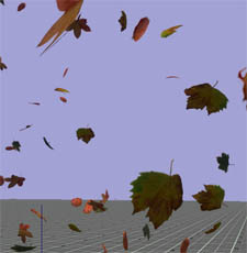
A good example of how to utilise mesh particle systems is the
falling_leaves particle system. In this system, several 3ds Max
leaf models share a single texture, but are rendered by the engine for the cost
of a single object.
The Mesh portion of this sub-panel contains the fields below:
| Field |
Description |
|---|
| Blend Mode |
Please refer to the description of the Blend Mode drop-down list box in
the Sprite group of fields. |
| Sorting |
Determines the quality of the alpha-blending sorting, and makes a trade-off
between quality and speed. The options are described in the table below:
| Option |
Description |
|---|
| None |
The particle system as a whole will be rendered in order with respect to other
sorted objects, and the triangles contained within will be sorted back to
front. The particles themselves, however, will be rendered out of order.
Choose this method if speed is paramount and the visual artifacts introduced
are not noticeable. |
| Quick |
Sorting will be done in a way that allows the renderer to still draw in groups
of 15.
This introduces some sorting inaccuracies, but maintains most of the speed of
unsorted mesh particles.
This method is highly recommended if the sorting inaccuracies are not
noticeable. |
| Accurate |
Sorting of individual objects and triangles is performed.
This provides the most accurate sorting, but breaks the ability of the
renderer to perform fast 15-at-a-time rendering, thus decreasing rendering
performance.
If you choose this sorting method, then make sure to double-check the
performance hit induced. | | |
| Visual |
Allows a regular mesh to be drawn as a particle system.
It does not support tint shaders, unless they have a specially written
shader, nor does it support blend modes like Mesh renderers. |
| Amp |
The Amp portion of this sub-panel contains the fields below:
| Field |
Description |
|---|
| Width |
Thickness in which to draw the image in the source file. |
| Steps |
Number of kinks in each line. |
| Length |
How compressed or elongated the original texture will be when rendering the
particle – the particle is composed of continuous segments of the
specified texture.
| | Variation |
Distance that each arc jumps away from the line, back to the origin. |
| Circular |
Indicates that the sprites should be drawn connecting each particle to the next,
instead of connecting each particle to the point of origin. | |
| Trail |
Draws a trail of particles behind each particle. Trail remembers the
particle's previous position, allowing you to use centrifugal forces like the
Orbitor component on the particle.
The Trail portion of this sub-panel contains the fields below:
| Field |
Description |
|---|
| Width |
Thickness in which to draw the image in the source file.
Try using small width values, as larger ones make the billboard
cross-visible. |
| Steps |
Number of times that the sprite will be drawn behind each particle, thus
actually altering the length of the trail. | |
| Blur |
Blur creates a trail of particles behind each particle.
The Blur portion of this sub-panel contains the fields below:
| Field |
Description |
|---|
| Width |
Thickness in which to draw the image in the source file. |
| Time |
How long to extend the particle back along its current velocity vector. |
Blur does not remember the particle's previous position. Instead, it
works by drawing multiple particles along one vector. So if you are going to
use Blur, it may not work as intended if you have centrifugal forces
controlling your particle. Instead, try Trail.
The figure below illustrates the key difference between Blur and
Trail.
Blur |
Trail |
|
Mesh particles are a type of visual that allow the user to render multiple objects in a single draw call. The above section describes how to create them.
Below are some of the examples of how mesh particles have been used to add clutter to the fantasy demo worlds.
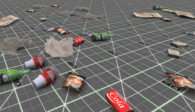
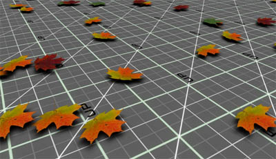
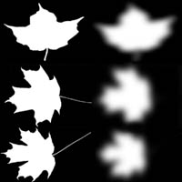
Examples of particle systems street_grim.xml, leaf_litter, and falling_leaves used in the fantasydemo.
In order to a mesh particle system to draw multiple objects in a single draw call, each of the objects must share a common texture map. The map below is used by all three leaf type sin the leaf_litter.xml particle system.

The Source sub-panel is shown below:
The table below describes some of the fields in this sub-panel:
| Field |
Description |
|---|
| Position |
Group of fields defining a space within which to create the particle. |
| Velocity |
Defines a set of velocities applied in local space that will be given to the particles on their
creation. |
Triggers/
Grounded |
Group of fields for time-triggered particle sub-systems.
It contains the fields described in the table below:
| Field |
Description |
|---|
| Time Trigger |
Indicates that the particle sub-systems will periodically generate particles. |
| Motion Trigger |
Causes particles to be emitted per distance traveled. This is useful for
creating a smoke trail behind a rocket, for example.
Select the System Properties and drag the system to preview the effect |
| Grounded |
Makes all particles spawn from the ground plane, provided they are within
Drop Distance of the it. |
|
| Particle Size |
Group of fields defining the limits for randomising the size of the particles. |
| Sprite Only |
Group of fields defining initial orientation and spin rate for sprite-based
particles. |
| Mesh Only |
Group of fields defining initial orientation and spin rate for mesh-based
particles. |
| Miscellaneous |
Assorted settings for the particle system.
It contains the fields described in the table below:
| Field |
Description |
|---|
Number Of Particles
To Spawn On Demand |
Number of particles to create, for non-continuous emitters.
This field is mandatory for non-continuous emitters, which are designed to be
dynamically created by the game (and not via WorldEditor). For these particle
systems, a game event must force the creation of particles. |
Allowed Time
To Create Particles |
Limits the time allowed to calculate particles – if particles are not
created within this time, then they are not spawned.
This is most useful for grounded particles, where system performance can be
affected by spawning too many particles. |
| The maximum speed |
Prevents the particle system from generating new particles if the system goes above the maximum speed setting. Select the System Properties and drag the system to preview the effect |
|
The Sink component removes particles from the world due to their age
or speed, and is shown below.
The table below describes the fields in this sub-panel:
| Field |
Description |
|---|
Maximum
Age |
Maximum number of seconds that the particles are allowed to exist.
A particle might be removed before its lifetime expires, if it reaches
Minimum Speed. |
Minimum
Speed |
Minimum speed that the particles may have before being removed.
A particle might be removed without reaching Minimum Speed if its
lifetime expires. |
The Barrier component creates a barrier of selectable shapes, which
depending on the selected barrier effect, will bounce, remove, wrap or allow particles
to pass through.
The table below describes the fields in this sub-panel:
| Field |
Description |
|---|
| Barrier Shape |
Shape of the Barrier. |
| Barrier Effect |
How the particles should interact with the barrier. |
The wrap barrier moves a particle from one side of the barrier to the other when it collides with the barrier edge. It is particularly useful for creating dens particle effects around the player like those used in weather systems.
A particle created at position 1. will hit the barrier at position 2 where it is teleported to position 3. This ensures that the density of particles remains high around the player.
The Force component applies a second force (separate to the initial velocity generator) to be applied to all particles in the sub-system. Force is applied in world space, so rotating the particle in WorldEditor will not rotate the direction that the force is applied.
The table below describes the fields in this sub-panel:
| Field |
Description |
|---|
| x |
Direction/magnitude of the force to be applied to the particles in the
sub-system. |
| y |
| z |
The Stream component is similar to the Force component, although it
allows control over how much force is imparted to each particle per time (via
the Half-Life field). Stream is applied in world space, so rotating the particle in WorldEditor will not rotate the direction that the stream is applied.
The table below describes the fields in this sub-panel:
| Field |
Description |
|---|
| Stream Direction |
Direction/magnitude of the force to be applied. |
| Half-Life |
Number of seconds that the particle's velocity will take to move halfway towards
the stream's velocity.
A large value will impart force slowly, while a short one will impart force
rapidly.
A negative number means infinite half-life, i.e., the particles will
not be affected by the stream. |
Drag can be simulated by setting the stream direction to (0,0,0), and the half life to <1.0
Allows the user to create a jittering/wobbling effect on both particle
position and/or velocity.
The table below describes the fields in this sub-panel:
| Field |
Description |
|---|
| Affect Position |
Check box |
Indicates that the jitter effect should be applied to the particles' positions. |
Drop-down
list box |
Shape within which the effect positions are created.
Larger objects result in larger differences in particle position, resulting
in a stronger jitter effect. |
| Affect Velocity |
Check box |
Indicates that the jitter effect should be applied to the particles' velocities. |
Drop-down
list box |
Shape within which the velocity vectors are created.
Larger objects result in larger effect vectors, resulting in a stronger
jitter effect. |
Position jitter actually teleports the particle to a new position defined by the distance of the jitter volume. This has implications for barriers and collisions. In the image below you can see that particles given a position jitter may escape a barrier volume because they can teleport through the barriers surface.
The Scaler component allows the user to scale the size of a particle
over time.
The table below describes the fields in this sub-panel:
| Field |
Description |
|---|
| Final Particle Size |
Final size of the particle (in metres).
Might be smaller than particle's original size. |
| Rate |
Number of metres per second by which to increase or decrease the particle. |
The Node Clamp component is used to determine that the generated
particles should be clamped to the origin of the particle sub-system.
There are no settings for this component.
The Orbitor sub-panel causes particles to orbit around a vertical line
along the y-axis.

The table below describes the fields in this sub-panel:
| Field |
Description |
|---|
| Orbit Y-Axis |
Coordinates of the point around which the particles will orbit along the
y-axis.
To have the particle orbit around a different axis while placed in the word,
simply rotate the particle sub-system in WorldEditor. |
| Angular Velocity |
Angular velocity of the orbit (in degrees per second). |
| Affect Velocity |
Indicates that the velocity should also be rotated with the particle.
If this if not selected, then the velocity will always be in the same
direction. |
The Flare component allows the user to specify that a certain number
of the particles should be spawned with a flare effect.
The table below describes the fields in this sub-panel:
| Field |
Description |
|---|
| Flare Name |
Texture used to apply the flare effect to the particles. |
| Flare Step |
Frequency in which to apply the flare effect to the particles.
0 means that the last spawned particle will have the flare.
1 means all particles have flares.
2..n means every nth particle will have the flare effect. |
| Colourise |
Determines whether to use the settings specified for the Tint Shader
component (if any) to colour the particles. |
| Use Particle Size |
Determines whether the particle should be sized as per its source file, instead
of using the size of the chosen texture for the flare. |
The Collide component is similar to the Barrier, except that it
uses the ground and other objects BSPs to calculate collisions.
Using this component can be expensive, so it is best to mix it in combination
with sub-systems that do not use it. This way, half the particles will pass
through the ground, but the effect will still be convincing, as the other half
will bounce.
The table below describes the fields in this sub-panel:
| Field |
Description |
|---|
| Elasticity |
Amount of bounce to apply to the particle when hitting the ground or other
objects (in which case their BSP trees are used for the calculation).
The elasticity is applied as a factor to which the incoming velocity should
be multiplied to determine the outgoing velocity.
For example, if Elasticity is set to 0.75 and a particle hits
the ground at a downward velocity of 1.0 m/s, then it will bounce upwards at a
velocity of 0.75 m/s. |
| Enable Sound |
Determines whether a sound should be played when particles hit the ground or
other objects. |
| Sound Tag |
Source file containing the sound to be played upon particle collision. |
| Source Src Idx |
Index (within the source file) of the sound to be played upon collision. |
The Matrix Swarm component allows particles to be attached to a node
or a list of nodes. This involves writing Python scripts in the game, in order
to attach this sub-system correctly.
Adding a Matrix Swarm component in ParticleEditor exposes the
functionality in the game script.
When the particle system is given a set of node matrices (by a programmer),
this option allows the particles to be attached to those nodes.
For example: There is an effect in the Fantasy demo Online mode when a guard is attacked with a fireball: The result is that lighting strobes all over his body. This effect was achieved using the Matrix Swarm feature.
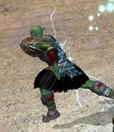
To understand how this effect is achieved take a look at the SFX person_explosion.xml in mf\fantasydemo\res\sfx. This file written by a programmer, contains a list of "SwarmTargets" that the programmer has defined for the particle system staff_implosion to spawn particles from.
The SFX file is simple to follow, it takes the staff_implosion particle system and plays (ForceParticle) the particle system on the models root node (ModelRoot). A single particle will spawn at each node sequentially from the top of the list downward and then repeat.
The Magnet component panel allows the user to specify a magnet effect
to the particle's point of origin.
The table below describes the fields in this sub-panel:
| Field |
Description |
|---|
| Magnet Strength |
Strength of the magnet.
Determines how strongly the particles are attracted to it, and how fast they
move in its direction. |
| Minimum Distance |
Area around the magnet in which it will not exert force. |
The Splat component is similar to the Collide one, except that
objects disappear when they hit the terrain or the world collision space.
Splat also notes the position the particle collides with the ground. This can then be used by the programmer to do things like add decals or spawn other effects
Particle systems need to be used with care, as they can easily have an
adverse effect on the game's performance. Consider the following:
Large particles using blending
may hinder performance (due to fill rate issues).
Each particle consumes memory
even if not being used (memory usage is shown in the status bar).
In the System Properties
sub-panel, set the Capacity field to be just enough to contain the number
of particles being used (see status bar).
The Amp and Trail particle
sub-systems (set in the Renderer Properties sub-panel) need to cache each
particle's history, and therefore consume considerably more memory.
For the purpose of previewing complex special effects and testing the alignment of hardpoints it can be useful to know a little Python.
Note: The FantasyDemo scripts use shortcut macros. If these macros are not configured within your scripts then the following shortcuts need to be replaced with their full notation.
$B = BigWorld
$p = BigWorld.player( )
$t =BigWorld.target( )
So that a command such as
$B.debugAQ($p.model)
becomes
BigWorld.debugAQ(BigWorld.player().model)
We can use Python to preview what a newly created weapon would look like in the player models hands.
Ensure that both your weapon model and player character share the same Hard Point. Open the client.
1 Enter the Python console by typing pressing ~(tilde) + P and type:
2 m = $B.Model("sets/town/props/axe.model")
3 $p.model.right_hand = m
4 press ~(tilde) + P to exit the Python console
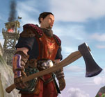
In summary we imported the BigWorld Model "sets/town/props/axe.model" and called it "m" (you would replace that path with the model you wanted to attach). We then attached "m" to the player models right hand.
We can use Python to play an action on a model. For example if we wanted to preview the Ranger swinging the axe that we just attached we could do the following.
1 Enter the Python console by typing pressing ~(tilde) + P and type:
2 $p.model.SwingSword()
If we wanted the Ranger to swing the sword whilst running we could type:
2 $p.model.SwingSword(); $p.model.RunForward()
4 press ~(tilde) + P to exit the Python console
We can use Python to test the alignment of a particle system to a model
I will use the alignment of staff_idle.xml to the staff model as an example.
1 Enter the Python console by typing pressing ~(tilde) + P and type:
2 m = $B.Model("sets/items/staff.model")
3 $p.model = m
4 import Pixie
5 p = Pixie.create("particles/staff_idle.xml")
6 m.node("HP_Spell").attach(p)
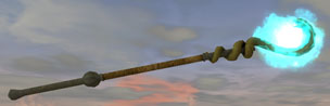
In summary we imported the BigWorld Model "sets/town/props/staff.model" and called it "m". We then swapped the player model for "m". We imported Pixie (particle module) so that we could add the particle system "staff_idle.xml" to the world. The staff_idle.xml particle system was then attached to the HP_Spell node of m.
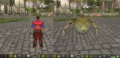
There are times when you might want to test current actions on a new character model asset that has been created. You can swap the player character models in the client via the Python console.
To do this follow this example command:
Open the Python console ( ~(tilde) + P) and type:
p = $B.Model ("characters/npc/spider/spider.model")
$p.model = p
This basically tells the client that you are assigning the value " p " to a Bigworld model, then swap the current player character model to this new " p " model.
Copyright 1999-2011 BigWorld Pty. Ltd. All rights reserved. Proprietary commercial in confidence.
 Special effects - A combination of mesh and particles
 Sub-system components
 Special effects - A combination of mesh and particles